22-5
Cisco 10000 Series Router Quality of Service Configuration Guide
OL-7433-09
Chapter 22 Hierarchical Scheduling and Queuing
MQC Hierarchical Queuing with 3-Level Scheduler
IP and PPP Session Shaping Using HQF
HQF treats IP and PPP sessions at the upper logical layer to provide bandwidth sharing and maximum
rate shaping. To shape IP or PPP sessions, apply a service policy to the sessions using a virtual template
or a RADIUS server.
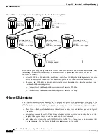
HQF allows the oversubscription of sessions on a subinterface (such as VLAN, QinQ, or VC) and at the
same time also allows oversubscription of the VLAN or VC on a physical port. During congestion, HQF
fairly shares the bandwidth first at the subinterface (lower logical layer) and then among the sessions
(upper logical layer). HQF takes the bandwidth that was distributed to the subinterface and fairly shares
it among the sessions of that subinterface. HQF then takes the bandwidth distributed to a session and
fairly shares it among the class queues of that session.
MQC Hierarchical Queuing with 3-Level Scheduler
The MQC Hierarchical Queuing with 3-Level Scheduler feature enables you to configure per-session
QoS and subinterface shaping of the aggregate session traffic. This feature provides a flexible packet
scheduling and queuing system in which you can specify how excess bandwidth is to be allocated among
the subscriber queues and logical interfaces. Rather than allocating an implicit minimum bandwidth
guarantee to each queue, the 3-level scheduler uses the bandwidth-remaining ratio parameter to allocate
unused bandwidth to each logical queue. The 3-level scheduler services queues based on the following
user-configurable parameters:
•
Maximum rate—The specified shape rate of the parent queue
•
Bandwidth-remaining ratio—The value used to determine the portion of unused, nonguaranteed
bandwidth allocated to a logical queue relative to other queues competing for the unused bandwidth
Note
At the class level, the router converts the values you specify for the
bandwidth
bps
and
bandwidth
remaining
percent
commands to a bandwidth-remaining ratio value. The router does not allow you to
configure the
bandwidth
bps
and
bandwidth remaining
percent
commands on the physical and logical
layers.
The 3-level scheduler on the PRE3 supports priority propagation by propagating the priority guarantees
you configure for subscriber services down to the logical interface level. Therefore, the priority traffic
is serviced first at the logical and class level. After servicing the priority traffic bandwidth, the 3-level
scheduler allocates unused bandwidth to the logical queues based on the configured
bandwidth-remaining ratio. In the default case, the 3-level scheduler allocates an equal share of the
unused bandwidth to each logical queue.
For ATM VCs, the 3-level scheduler shares bandwidth proportionally to each VC’s bandwidth, if no
bandwidth remaining ratio (BRR) or VC weight is configured. For other types of subinterfaces, the
scheduler distributes the bandwidth equally, unless BRR is configured. The scheduler uses a default BRR
value of 1 if BRR is not specified, except for the ATM logical layer as mentioned above. The logical
layer BRR is completely independent from the BRRs configured at the class layer.
The 3-level scheduler supports shaping and scheduling only on the egress interface. The
bandwidth
command must be configured as a percentage of the available bandwidth or as an absolute bandwidth.
You cannot concurrently configure the
bandwidth
and
bandwidth remaining
commands on the same
class queue or the same policy map.
For more information about the bandwidth-remaining ratio, see the
“Distribution of Remaining
Bandwidth Using Ratio” section on page 5-14
.

