


C H A P T E R
9-1
Cisco ONS 15454 Installation and Operations Guide
November 2001
9
Ethernet Operation
The Cisco ONS 15454 integrates Ethernet into a SONET time-division multiplexing (TDM) platform.
Unlike traditional transport products, which map Ethernet frames directly over dedicated TDM
bandwidth, the ONS 15454 incorporates layer 2 switching to allow more efficient data transport over the
existing SONET backbone.
This chapter describes the Ethernet capabilities of the ONS 15454, including:
•
Ethernet cards
•
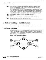
Multicard and Single-card Etherswitch
•
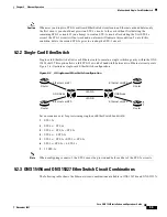
Ethernet circuit combinations and configurations
•
VLAN and IEEE 802.1Q support
•
Spanning tree and IEEE 802.1D support
•
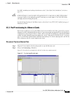
Ethernet performance and maintenance screens
•
Ethernet alarm thresholds (RMON)
9.1 Ethernet Cards
The ONS 15454 shelf assembly holds up to ten Ethernet cards in any multispeed slot. Ethernet cards
include the E100T-12, E100T-G, E1000-2 and E1000-2-G. The E100T-12 is the functional equivalent of
the E100T-G, and the E1000-2 is the functional equivalent of the E1000-2-G. An ONS 15454 using
XC10G cards requires the G versions of the Ethernet cards.
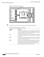
Ethernet card faceplates have two card-level LEDs and a pair of port-level LEDs next to each port.
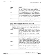
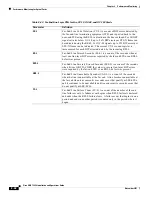
Table 9-1
Card-level LEDS
LED State
Description
Red FAIL LED
The red FAIL LED indicates that the card’s processor is not ready or a
catastrophic software failure occurred on the Ethernet card. As part of the
boot sequence, the FAIL LED is turned on until the software deems the card
operational.
Green ACT LED
A green ACT LED provides the operational status of the E100T-G. When the
ACT LED is green it indicates that the Ethernet card is active and the
software is operational.


