


9-11
Cisco ONS 15454 Installation and Operations Guide
November 2001
Chapter 9 Ethernet Operation
Ethernet Circuit Configurations
For shared packet ring Ethernet, valid circuit sizes are STS-1, STS-3C and STS-6c.
Step 14
Verify that the Bidirectional checkbox is checked.
Note
You must manually provision the circuits if you are building a shared packet ring
configuration.
Step 15
Click Next.
The Circuit Creation (Circuit Source) dialog box opens.
Step 16
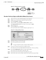
From the Node menu, choose the circuit source.
Any shared packet ring node can serve as the circuit source.
Step 17
Choose Ethergroup from the Slot menu and click Next.
The Circuit Creation (Circuit Destination) dialog box opens.
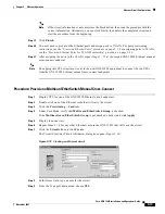
Step 18
Choose the circuit destination from the Node menu.
Step 19
Except for the source node, any shared packet ring node can serve as the circuit destination.
Step 20
Choose Ethergroup from the Slot menu and click Next.
The Circuit Creation (Circuit VLAN Selection) dialog box opens.
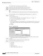
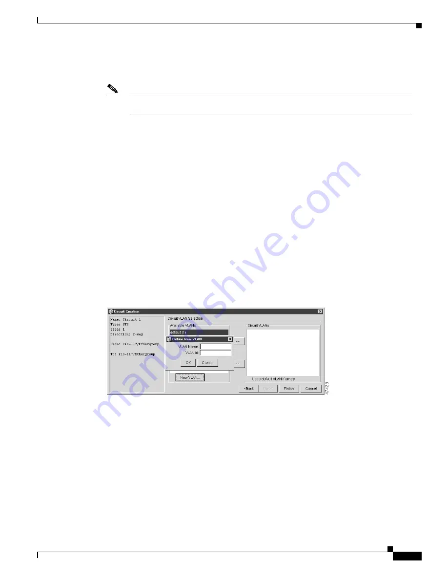
Step 21
Create the VLAN:
a.
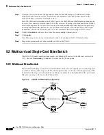
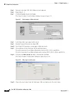
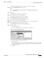
Click the New VLAN tab.
The Circuit Creation (Define New VLAN) dialog box opens
(Figure 9-10).
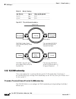
Figure 9-10 Choosing a VLAN name and ID
b.
Assign an easily-identifiable name to your VLAN.
c.
Assign a VLAN ID.
This VLAN ID number must be unique. It is usually the next available number not already assigned
to an existing VLAN (between 2 and 4093). Each ONS 15454 network supports a maximum of 509
user-provisionable VLANs.
d.
Click OK.


