background image

 Preparing to Install the Router 2-17

Serial Connections

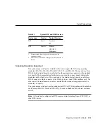
Balanced drivers allow EIA/TIA-449 signals to travel greater distances than EIA/TIA-232
signals. The recommended distance limits for EIA/TIA-449 shown in Table 2-2 are also
valid for V.35, X.21, and EIA-530. Typically, EIA/TIA-449 and EIA-530 can support
2-Mbps rates, and V.35 can support 4-Mbps rates.

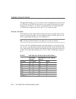
Asynchronous/Synchronous Serial Module Baud Rates

The following baud-rate limitations apply to the slow-speed serial interfaces found in the
asynchronous/synchronous serial modules:

Asynchronous interface—Maximum baud rate is 115.2 kbps.

Synchronous interface—Maximum baud rate is 128-kbps full duplex.

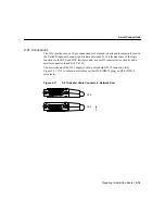
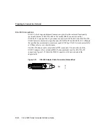
EIA/TIA-232 Connections

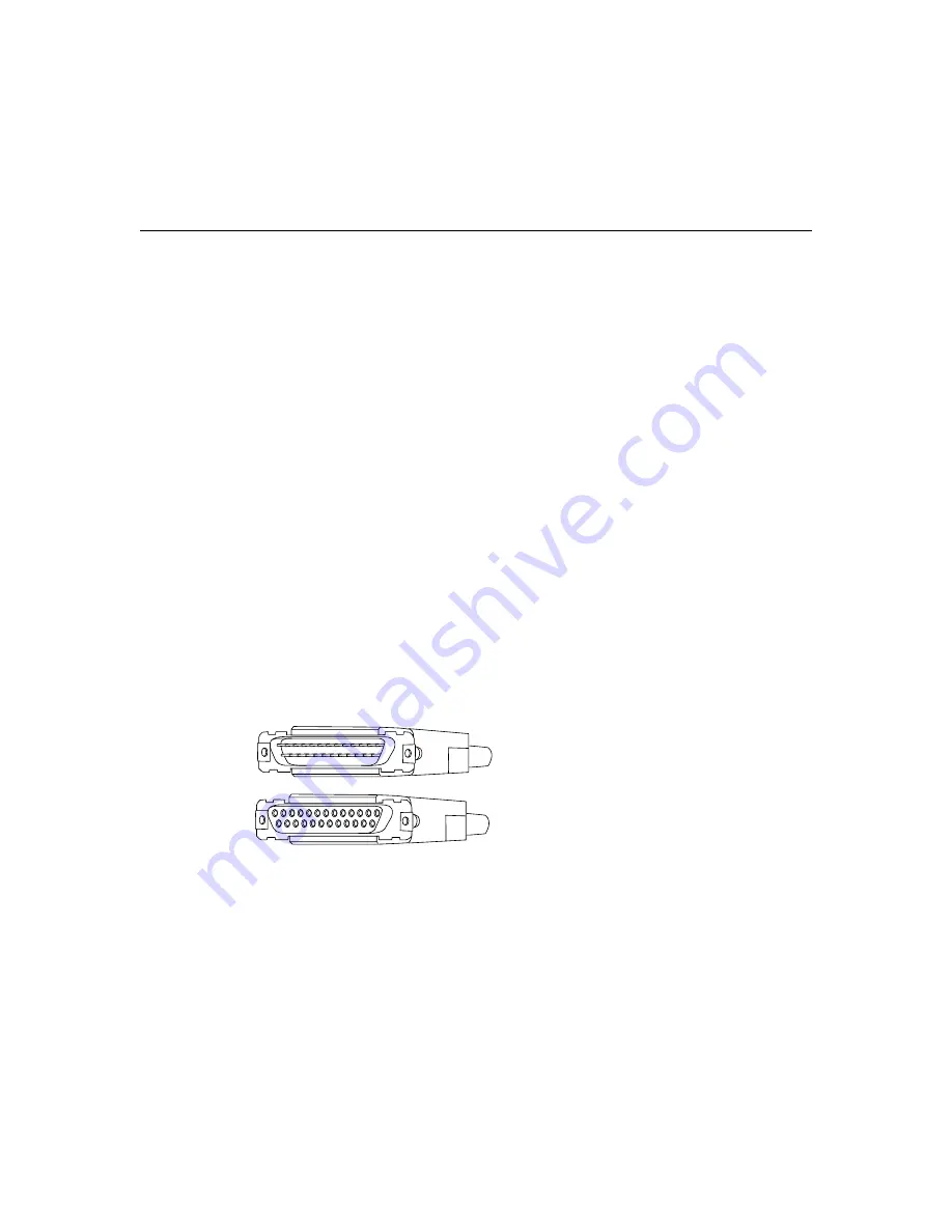
EIA/TIA-232 supports unbalanced circuits at signal speeds up to 64 kbps. The network end
of the adapter cable is a standard 25-pin D-shell connector known as a DB-25. (See
Figure 2-8.) The router console and auxiliary ports also use EIA/TIA-232 connections;
however, the serial module ports support synchronous connections, and the console and
auxiliary ports support asynchronous connections.

Figure 2-8

EIA/TIA-232 Adapter Cable Connectors, Network End

EIA/TIA-449 Connections

EIA/TIA-449, which supports balanced (EIA/TIA-422) and unbalanced (EIA/TIA-423)
transmissions, is a faster version of EIA/TIA-232 (up to 2 Mbps) that provides more
functions and supports transmissions over greater distances.

 H1343a

DTE

DCE

Summary of Contents for 2621

Page 1: ...ware configuration information refer to the Cisco IOS configuration guide and command reference publications These publications are available on the Documentation CD ROM that came with your router or you can order printed copies See the Ordering Documentation section on page xi This publication describes a variety of router models that are similar in functionality but differ in the number of inter...

Page 2: ...he various ports and how to prepare for connections between networks and ports Chapter 3 Installing the Router Includes basic installation information and discusses making connections to your LAN WAN and console terminal Appendix A Troubleshooting the Router Discusses how to isolate problems and read the LEDs Appendix B Maintaining the Router Discusses selected maintenance procedures Appendix C Us...

Page 3: ...ph Caution This symbol means reader be careful In this situation you might do something that could result in equipment damage or loss of data Warning This warning symbol means danger You are in a situation that could cause bodily injury Before you work on any equipment be aware of the hazards involved with electrical circuitry and be familiar with standard practices for preventing accidents To see...

Page 4: ...trischen Stromkreisen verbundenen Gefahren und der Standardpraktiken zur Vermeidung von Unfällen bewußt Übersetzungen der in dieser Veröffentlichung enthaltenen Warnhinweise finden Sie im Dokument Regulatory Compliance and Safety Information Informationen zu behördlichen Vorschriften und Sicherheit das zusammen mit diesem Gerät geliefert wurde Avvertenza Questo simbolo di avvertenza indica un peri...

Page 5: ...nto Regulatory Compliance and Safety Information Informação de Segurança e Disposições Reguladoras que acompanha este dispositivo Advertencia Este símbolo de aviso significa peligro Existe riesgo para su integridad física Antes de manipular cualquier equipo considerar los riesgos que entraña la corriente eléctrica y familiarizarse con los procedimientos estándar de prevención de accidentes Para ve...

Page 6: ...ternet e mail and it is excellent for quick access to information over lower bandwidths The WWW version of CCO provides richly formatted documents with photographs figures graphics and video as well as hyperlinks to related information You can access CCO in the following ways WWW http www cisco com WWW http www europe cisco com WWW http www china cisco com Telnet cco cisco com Modem From North Ame...

Page 7: ...it might be more current than printed documentation To order additional copies of the Documentation CD ROM contact your local sales representative or call customer service The CD ROM package is available as a single package or as an annual subscription You can also access Cisco documentation on the World Wide Web at http www cisco com http www china cisco com or http www europe cisco com If you ar...

Page 8: ...Ordering Documentation Book Title xii ...

Page 9: ...o 2600 Series LAN Interfaces Hardware Features In addition to the interfaces listed in Table 1 1 the routers include the following hardware features Dynamic random access memory DRAM for main memory and shared memory Nonvolatile random access memory NVRAM for storing configuration information Model Ethernet 10BaseT Token Ring RJ 45 Fast Ethernet 10 100 Network Module Slot WAN Interface Card Slots ...

Page 10: ... SERIAL 1 SERIAL 0 CONN CONN WIC 2A S SEE MANUAL BEFORE INSTALLATION SERIAL 1 SERIAL 0 CONN CONN WIC 2T Cisco 2610 W1 100 240V 1A 50 60 Hz 47 W W0 AUX CONSOLE ETHERNET 0 ACT LINK Ethernet 0 0 10BaseT port RJ 45 Auxiliary port RJ 45 Console port RJ 45 Cisco 2610 H11580 SEE MANUAL BEFORE INSTALLATION SERIAL 1 SERIAL 0 CONN CONN WIC 2A S SEE MANUAL BEFORE INSTALLATION SERIAL 1 SERIAL 0 CONN CONN WIC ...

Page 11: ...0 240V 1A 50 60 Hz 47 W W0 AUX CONSOLE ETHERNET 0 ACT LINK ACT TOKEN RING 1 LINK W1 Ethernet 0 0 10BaseT port RJ 45 Token Ring 0 0 RJ 45 H11582 Cisco 2612 Auxiliary port RJ 45 Console port RJ 45 SEE MANUAL BEFORE INSTALLATION SERIAL 1 SERIAL 0 CONN CONN WIC 2A S SEE MANUAL BEFORE INSTALLATION SERIAL 1 SERIAL 0 CONN CONN WIC 2T Cisco 2611 100 240V 1A 50 60 Hz 47 W W0 AUX CONSOLE ACT ACT TOKEN RING ...

Page 12: ...umentation CD ROM that accompanied your router and on Cisco Connection Online See the Ordering Documentation section on page xi and the section Cisco Connection Online on page x SEE MANUAL BEFORE INSTALLATION SERIAL 1 SERIAL 0 CONN CONN WIC 2A S SEE MANUAL BEFORE INSTALLATION SERIAL 1 SERIAL 0 CONN CONN WIC 2T Cisco 2610 W1 100 240V 1A 50 60 Hz 47 W W0 AUX CONSOLE ETHERNET 0 ACT LINK 10 100BaseT E...

Page 13: ...47W maximum 260 Btus1 hr 1 Btus British thermal units Input voltage DC power supply Current Power dissipation 40W 38 to 75 VDC 2 0A 47W maximum 260 Btus hr Processor 40 MHz Motorola PowerQUICC MPC860 Operating environment 32 to 104 F 0 to 40 C Nonoperating temperature 130 to 158 F 25 to 70 C Operating humidity 5 to 95 noncondensing Noise level 38 dBa minimum Regulatory compliance FCC Class B and C...

Page 14: ...determine whether your equipment is causing interference by turning it off If the interference stops it was probably caused by the Cisco equipment or one of its peripheral devices If the equipment causes interference to radio or television reception try to correct the interference by using one or more of the following measures Turn the television or radio antenna until the interference stops Move ...

Page 15: ...ling the Router for installation instructions Safety Recommendations Follow these guidelines to ensure general safety Keep the chassis area clear and dust free during and after installation Put the removed chassis cover in a safe place Keep tools away from walk areas where you and others could fall over them Do not wear loose clothing that could get caught in the chassis Fasten your tie or scarf a...

Page 16: ...should be allowed to install or replace this equipment Warning Before working on a chassis or working near power supplies unplug the power cord on AC units disconnect the power at the circuit breaker on DC units Warning Ultimate disposal of this product should be handled according to all national laws and regulations Warning Ultimate disposal of this product should be handled according to all appl...

Page 17: ...ing Before working on a chassis or working near power supplies unplug the power cord on AC units disconnect the power at the circuit breaker on DC units Warning Do not touch the power supply when the power cord is connected For systems with a power switch line voltages are present within the power supply even when the power switch is OFF and the power cord is connected For systems without a power ...

Page 18: ...res Always follow ESD prevention procedures when removing and replacing components Ensure that the chassis is electrically connected to earth ground Wear an ESD preventive wrist strap ensuring that it makes good skin contact Connect the clip to an unpainted surface of the chassis frame to safely channel unwanted ESD voltages to ground To properly guard against ESD damage and shocks the wrist strap...

Page 19: ...nd help you avoid environmentally caused equipment failures Ensure that the room in which you operate your system has adequate air circulation Electrical equipment generates heat Ambient air temperature might not be able to cool equipment to acceptable operating temperatures without adequate circulation Always follow the ESD prevention procedures described in the Preventing Electrostatic Discharge...

Page 20: ... in the rack which can be found by experimenting with different arrangements Power Supply Considerations Check the power at your site to ensure that you are receiving clean power free of spikes and noise Install a power conditioner if necessary The router power supply includes the following features Autoselects either 110V or 220V operation All units include a 6 foot 1 8 meter electrical power cor...

Page 21: ...2 pair Category 5 or unshielded twisted pair UTP straight through RJ 45 cable 10Base2 Ethernet on thin coaxial cable also known as thin Ethernet The maximum segment distance is 607 feet 186 meters 10Base5 Ethernet on thick coaxial cable also known as thick Ethernet The maximum segment distance is 1 640 feet 500 meters 10BaseT Ethernet on UTP cable The maximum segment distance is 328 feet 100 meter...

Page 22: ... Ring port See Figure 2 3 The Cisco 2620 provides one 10 100BaseT Ethernet port See Figure 2 4 The Cisco 2621 provides two 10 100BaseT Ethernet ports See Figure 2 5 Figure 2 1 Cisco 2610 Ethernet Connections SEE MANUAL BEFORE INSTALLATION SERIAL 1 SERIAL 0 CONN CONN WIC 2A S SEE MANUAL BEFORE INSTALLATION SERIAL 1 SERIAL 0 NN CONN WIC 2A S Cisco 2610 W0 W1 AUX CONSOLE ETHERNET 0 0 ACT LINK H11583 ...

Page 23: ...E INSTALLATION SERIAL 1 SERIAL 0 CONN CONN WIC 2A S SEE MANUAL BEFORE INSTALLATION SERIAL 1 SERIAL 0 NN CONN WIC 2A S Cisco 2611 W0 AUX CONSOLE ETHERNET 0 0 ACT LINK ACT ETHERNET 0 1 LINK Ethernet 0 0 10BaseT port RJ 45 Ethernet 0 1 10BaseT port RJ 45 Auxiliary port RJ 45 Console port RJ 45 Link LED ACT LED Link LED ACT LED ...

Page 24: ...NN CONN WIC 2A S Cisco 2612 W0 AUX CONSOLE ETHERNET 0 0 ACT LINK ACT TOKEN RING 0 0 LINK Ethernet 0 0 10BaseT port RJ 45 Token Ring 0 0 RJ 45 Link LED ACT LED Link LED ACT LED Auxiliary port RJ 45 Console port RJ 45 SEE MANUAL BEFORE INSTALLATION SERIAL 1 SERIAL 0 CONN CONN WIC 2A S SEE MANUAL BEFORE INSTALLATION SERIAL 1 SERIAL 0 NN CONN WIC 2A S Cisco 2620 W0 Link FDX AUX CONSOLE 10 100 ETHERNET...

Page 25: ...SERIAL 0 CONN CONN WIC 2A S SEE MANUAL BEFORE INSTALLATION SERIAL 1 SERIAL 0 CONN CONN WIC 2A S Cisco 2621 W0 W1 AUX CONSOLE 10 100 ETHERNET 0 0 10 100 ETHERNET 0 1 10 100BaseT Ethernet 0 0 RJ 45 10 100BaseT Ethernet 0 1 RJ 45 Auxiliary port RJ 45 Console port RJ 45 FDX LED FDX LED Link FDX FDX Link LED 100 Mbps Mbps LED Link Link LED 100 Mbps Mbps LED ...

Page 26: ... single Token Ring interface See Figure 2 7 Figure 2 6 Cisco 2612 Ethernet and Token Ring Connections H11585 SEE MANUAL BEFORE INSTALLATION SERIAL 1 SERIAL 0 CONN CONN WIC 2A S SEE MANUAL BEFORE INSTALLATION SERIAL 1 SERIAL 0 NN CONN WIC 2A S Cisco 2612 W0 AUX CONSOLE ETHERNET 0 0 ACT LINK ACT TOKEN RING 0 0 LINK Ethernet 0 0 10BaseT port RJ 45 Token Ring 0 0 RJ 45 Link LED ACT LED Link LED ACT LE...

Page 27: ...erent ring speeds 4 and 16 Mbps All devices on the Token Ring must use the same operating speed Use the provided Token Ring cable to connect the router to a switch Refer to the section Token Ring Port Pinouts in the online document Cisco Modular Access Router Cabling Specifications for the Token Ring port pinouts This document is on the Documentation CD ROM that accompanied your router package and...

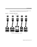
Page 28: ... synchronous serial interface Type of connector male or female required to connect to the device Signaling standard required by the device Configuring Serial Connections The serial ports on the asynchronous synchronous serial network modules and the serial WAN interface card use DB 60 connectors See Figure 2 8 through Figure 2 12 and Figure 2 13 Serial ports can be configured as DTE or DCE dependi...

Page 29: ...or which connects to the DB 60 port on a serial WAN interface card The other end of the serial transition cable is available with a connector appropriate for the standard you specify The synchronous serial port can be configured as DTE or DCE depending on the attached cable except EIA 530 which is DTE only To order a shielded cable contact customer service Note All serial ports configured as DTE r...

Page 30: ...ce limits beyond which a signal significantly degrades or is completely lost Note Only the serial WAN interface card supports bit rates above 128 kbps Table 2 2 lists the recommended maximum speeds and distances for each serial interface type however you might get good results at speeds and distances greater than those listed if you understand the electrical problems that might arise and can compe...

Page 31: ...s Synchronous interface Maximum baud rate is 128 kbps full duplex EIA TIA 232 Connections EIA TIA 232 supports unbalanced circuits at signal speeds up to 64 kbps The network end of the adapter cable is a standard 25 pin D shell connector known as a DB 25 See Figure 2 8 The router console and auxiliary ports also use EIA TIA 232 connections however the serial module ports support synchronous connec...

Page 32: ...he EIA TIA 449 adapter cable provides a standard 37 pin D shell connector See Figure 2 9 EIA TIA 449 cables are available as either DTE DB 37 plug or DCE DB 37 receptacle Figure 2 9 EIA TIA 449 Adapter Cable Connectors Network End V 35 Connections The V 35 interface is recommended for speeds up to 48 kbps although it is often used successfully at 4 Mbps The network end of the V 35 adapter cable pr...

Page 33: ...a networks X 21 relocates some of the logic functions to the DTE and DCE interfaces and as a result requires fewer circuits and a smaller connector than EIA TIA 232 The network end of the X 21 adapter cable is a standard DB 15 connector See Figure 2 11 X 21 cables are available as either DTE DB 15 plug or DCE DB 15 receptacle Figure 2 11 X 21 Adapter Cable Connectors Network End 1 8 15 9 DCE DTE H...

Page 34: ...A TIA 449 EIA 530 refers to the electrical specifications of EIA TIA 422 and EIA TIA 423 Although the specification recommends a maximum speed of 2 Mbps EIA 530 is used successfully at 4 Mbps or faster over short distances The EIA 530 adapter cable is available in DTE mode only The network end of the EIA 530 adapter cable is a standard DB 25 plug commonly used for EIA TIA 232 connections Figure 2 ...

Page 35: ...l transition cables you can connect to the DB 60 port on the asynchronous synchronous serial modules and serial WAN interface card Figure 2 13 Serial Interface Adapter Cables Router connections EIA TIA 449 V 35 X 21 Network connections at the modem or CSU DSU H2485 EIA TIA 232 EIA 530 ...

Page 36: ...odular Access Router Cabling Specifications for pinouts This document is located on both the Documentation CD ROM that accompanied your router package and Cisco Connection Online Warning Network hazardous voltages are present in the BRI cable If you detach the BRI cable detach the end away from the router first to avoid possible electric shock Network hazardous voltages also are present on the sys...

Page 37: ...SU WAN interface card For more information on Switched 56 kbps WAN interface cards see the publication Cisco WAN Interface Cards Hardware Installation Guide included in your router package Table 2 3 ISDN BRI Cable Specifications Specification High Capacitance Cable Low Capacitance Cable Resistance at 96 kHz 160 ohms km 160 ohms km Capacitance at 1 kHz 120 nF1 km 1 nF nanoFarad 30 nF km Impedance a...

Page 38: ...Preparing to Connect to a Network Cisco 2600 Series Hardware Installation Guide 2 24 ...

Page 39: ...tions Required Tools and Equipment on page 3 2 Setting Up the Chassis on page 3 3 Connecting the DC Power Supply on page 3 10 Connecting to a Network on page 3 14 Connecting the Console Terminal and Modem on page 3 18 What to Do after Installing the Router Hardware on page 3 22 Warning Only trained and qualified personnel should be allowed to install or replace this equipment ...

Page 40: ...cluded Token Ring lobe cable for connection to the Token Ring port included Note For more information on cable specifications see the document Cisco Modular Access Router Cabling Specifications on the Documentation CD ROM that accompanied your router package and on Cisco Connection Online For cable ordering information see the Obtaining Service and Support section on page ix Ethernet 10BaseT hub o...

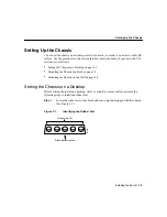
Page 41: ... Setting the Chassis on a Desktop on page 3 3 Mounting the Chassis in a Rack on page 3 5 Mounting the Chassis on the Wall on page 3 8 Setting the Chassis on a Desktop Before setting the router on a desktop shelf or other flat secure surface perform the following steps to install the rubber feet Step 1 Locate the rubber feet on the black adhesive strip that shipped with the chassis See Figure 3 1 F...

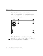
Page 42: ...dhesive strip and place them adhesive side down onto the five round recessed areas on the bottom of the chassis See Figure 3 2 Figure 3 2 Installing the Rubber Feet Step 4 Place the router right side up on a flat smooth secure surface Caution Do not place anything on top of the router that weighs more than 10 pounds 4 5 kg Excessive weight on top could damage the chassis Fan H4795 ...

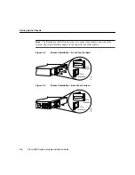
Page 43: ...e bottom of the rack If the rack contains stabilizing devices install the stabilizers prior to mounting or servicing the unit in the rack Figure 3 3 Identifying the Brackets Attaching the Brackets To install the chassis in a rack attach the brackets in one of the following ways With the front panel forward see Figure 3 4 With the rear panel forward see Figure 3 5 In a center mount telco rack with ...

Page 44: ...ollow show how to connect the bracket to one side of the chassis The second bracket connects to the opposite side of the chassis Figure 3 4 Bracket Installation Front Panel Forward Figure 3 5 Bracket Installation Rear Panel Forward H7821 19 in brackets 24 in brackets H6329 19 in brackets 24 in brackets ...

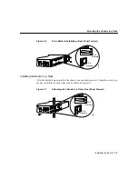
Page 45: ...Installing the Router in a Rack After the brackets are secured to the chassis you can rack mount it Using the screws you provide attach the chassis to the rack as shown in Figure 3 7 Figure 3 7 Attaching the Chassis to a Rack Rear Panel Forward H6330 19 in brackets 24 in brackets H6331 19 in brackets 24 in brackets ...

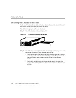
Page 46: ...s Step 2 Attach the chassis assembly to the wall as shown in Figure 3 9 using screws and anchors that you provide We recommend the following For the best support of the chassis and cables attach the brackets so that the screws align with a vertical wall stud See Figure 3 9 This position will prevent the chassis from pulling away from the wall when cables are attached For the best ventilation of th...

Page 47: ...9 Mounting the Chassis on the Wall H11579 SEE MANUAL BEFORE INSTALLATION SERIAL 1 SERIAL 0 CONN CONN WIC 2A S SEE MANUAL BEFORE INSTALLATION SERIAL 1 SERIAL 0 CONN CONN WIC 2A S Cisco 2611 100 240V 1A 50 60 Hz 47 W W0 AUX CONSOLE ETHERNET 0 ACT LINK ACT ETHERNET 1 LINK ...

Page 48: ...ironments Table 3 1 lists the power supply specifications Warning This unit is intended for installation in restricted access areas A restricted access area is where access can only be gained by service personnel through the use of a special tool lock and key or other means of security and is controlled by the authority responsible for the location Table 3 1 DC Power Supply Specifications Descript...

Page 49: ...nd to ground positive to positive line to L and negative to negative neutral to N Note that the ground wire should always be connected first and disconnected last Warning When stranded wiring is required use approved wiring terminations such as closed loop or spade type with upturned lugs These terminations should be the appropriate size for the wires and should clamp both the insulation and condu...

Page 50: ...icted access areas and is approved for use with 14 AWG copper conductors only The installation must comply with all applicable codes Take the following steps to wire the terminal block Step 1 Attach the appropriate lugs at the wire end of the power supply cord Step 2 Wire the DC power supply to the terminal block as shown in Figure 3 10 ...

Page 51: ... Router 3 13 Wiring the DC Power Supply Figure 3 10 DC Power Supply Connections Terminal block Negative Input 40 72V Current 1 5 1 0A Watts 40W On off switch Positive Ground Terminal block cover Terminal block H2275 ...

Page 52: ...ling Specifications available on the Documentation CD ROM that came with your router and on Cisco Connection Online Note Although the illustrations in this section show the Cisco 2611 router the procedures are the same for all of the Cisco 2600 series routers Depending on your router model do one of the following to connect your router to a network Cisco 2610 or Cisco 2611 Connect the Ethernet 10B...

Page 53: ...2 To ensure agency compliance with electromagnetic emissions requirements EMI ensure that the lobe cable is shielded SEE MANUAL BEFORE INSTALLATION SERIAL 1 SERIAL 0 CONN CONN WIC 2A S SEE MANUAL BEFORE INSTALLATION SERIAL 1 SERIAL 0 CONN CONN WIC 2A S Cisco 2611 100 240V 1A 50 60 Hz 47 W W0 AUX CONSOLE ETHERNET 0 ACT LINK ACT ETHERNET 1 LINK 10BaseT cable Ethernet 10BaseT port RJ 45 10BaseT hub o...

Page 54: ...ly to a switch such as a Cisco Catalyst 3900 TX 1 2 3 4 5 6 7 8 9 10 11 12 13 14 15 16 17 18 19 20 PWR MODE RESET SYSREQ FAULT RX ATTACH STACK EIA 232 Catalyst 3900 RJ 11 twisted pair SEE MANUAL BEFORE INSTALLATION SERIAL 1 SERIAL 0 CONN CONN WIC 2A S SEE MANUAL BEFORE INSTALLATION SERIAL 1 SERIAL 0 CONN CONN WIC 2A S Cisco 2611 100 240V 1A 50 60 Hz 47 W W0 AUX CONSOLE ETHERNET 0 ACT LINK ACT ETHE...

Page 55: ...L BEFORE INSTALLATION SERIAL 1 SERIAL 0 CONN CONN WIC 2A S SEE MANUAL BEFORE INSTALLATION SERIAL 1 SERIAL 0 CONN CONN WIC 2A S Cisco 2611 100 240V 1A 50 60 Hz 47 W W0 AUX CONSOLE ETHERNET 0 ACT LINK ACT ETHERNET 1 LINK 10 100BaseT cable Ethernet 10 100BaseT port RJ 45 10 100BaseT hub or switch 14875 ...

Page 56: ... console and auxiliary ports You can identify a rollover cable by comparing the two modular ends of the cable Holding the cables side by side with the tab at the back the wire connected to the pin on the outside of the left plug should be the same color as the wire connected to the pin on the outside of the right plug See Figure 3 14 If your cable came from Cisco Systems pin 1 will be white on one...

Page 57: ... to RJ 45 rollover cable looks like a telephone cable and an RJ 45 to DB 9 or RJ 45 to DB 25 adapter labeled TERMINAL included with the router See Figure 3 15 Step 2 Configure your terminal or PC terminal emulation software for 9600 baud 8 data bits no parity and 2 stop bits For information on console port pinouts see the online document Cisco Modular Access Router Cabling Specifications on the Do...

Page 58: ...EE MANUAL BEFORE INSTALLATION SERIAL 1 SERIAL 0 CONN CONN WIC 2A S SEE MANUAL BEFORE INSTALLATION SERIAL 1 SERIAL 0 CONN CONN WIC 2A S Cisco 2611 100 240V 1A 50 60 Hz 47 W W0 AUX CONSOLE ETHERNET 0 ACT LINK ACT ETHERNET 1 LINK RJ 45 to RJ 45 rollover cable RJ 45 to DB 9 or RJ 45 to DB 25 adapter Console port RJ 45 Laptop computer H11493 ...

Page 59: ...ter See Figure 3 16 Step 2 Make sure that your modem and the auxiliary port on the router are configured for the same transmission speed 38400 baud is typical and hardware flow control with Data Carrier Detect DCD and Data Terminal Ready DTR operations For information on console port pinouts see the online document Cisco Modular Access Router Cabling Specifications on the Documentation CD ROM that...

Page 60: ...not power on proceed to Appendix A Troubleshooting the Router Use the Software Configuration Guide for Cisco 3600 series and Cisco 2600 series routers included in your router package for initial software configuration information SEE MANUAL BEFORE INSTALLATION SERIAL 1 SERIAL 0 CONN CONN WIC 2A S SEE MANUAL BEFORE INSTALLATION SERIAL 1 SERIAL 0 CONN CONN WIC 2A S Cisco 2611 100 240V 1A 50 60 Hz 47...

Page 61: ...ocedures are available on the Documentation CD ROM that shipped with the router To see translated versions of warnings in this appendix see the Regulatory Compliance and Safety Information document that accompanied your router Caution Before opening the chassis be sure that you have discharged all static electricity from your body and the power is OFF Before performing any procedures described in ...

Page 62: ...he following appears Cisco 2610 MPC860 processor revision 0x200 with 28672K 4096K bytes of memory This line shows how much memory is installed in this example 28672K 4096K The first number represents primary memory and the second number represents shared memory Cisco 2600 DRAM Cisco 2600 series routers contain two 100 pin dual in line memory module DIMM sockets or banks for DRAM numbered 0 and 1 S...

Page 63: ...ear panel of the router Step 3 Remove the screws located on the top of the chassis Note that the chassis is comprised of two sections top and bottom Step 4 Holding the chassis with both hands position it as shown in Figure B 1 Step 5 Slide the top section away from the bottom section as shown in Figure B 2 Warning Do not touch the power supply when the power cord is connected For systems with a po...

Page 64: ...ries Hardware Installation Guide Opening the Chassis B 4 Figure B 1 Holding Chassis for Cover Removal Figure B 2 Removing Chassis Cover POWER RPS ACTIVITY Cisco 2600SERIES H11659 POWER RPS ACTIVITY Cisco 2600SERIES ...

Page 65: ...p cover is off set it aside Figure B 3 shows the layout of the system cards Figure B 3 System Card Layout H11599 Ethernet Console AUX Ethernet Primary memory DRAM DIMMs Lattice U23 Advanced Interface Module AIM System code SIMM Flash memory Boot ROM Pin 1 Duart reset Reset ...

Page 66: ...n ESD preventive wrist strap Step 3 Open the cover following the instructions in the Opening the Chassis section on page B 3 Step 4 Remove the existing DRAM DIMM by pulling outward on the connectors to unlatch them as shown in Figure B 4 Be careful not to break the holders on the DIMM connector Caution To prevent damage do not press on the center of the DIMMs Handle each DIMM carefully ...

Page 67: ...r B 7 DRAM DIMM Installation Step 5 Position the new DIMM so that the polarization notch is located at the left end of the DIMM socket as shown in Figure B 4 Figure B 4 Removing and Replacing the DRAM DIMM 10243 1 1 2 1 2 2 ...

Page 68: ...lash memory 80 pin single in line memory module SIMM Tools Required You will need the following tools to remove and replace the system code SIMM on the router Medium size flat blade screwdriver 1 4 inch 0 625 cm Electrostatic discharge ESD preventive wrist strap System code SIMM Preparing to Install the System Code SIMM There is one system code Flash memory SIMM socket on the system board You can ...

Page 69: ...Step 1 If you have not already done so enter the copy flash tftp EXEC command to back up the system code Step 2 Power OFF the router Step 3 Remove all cables from the rear panel of the router Step 4 Attach an ESD preventive wrist or ankle strap Step 5 Open the chassis cover following the procedure in the Opening the Chassis section on page B 3 Step 6 Locate the system code SIMM on the system card ...

Page 70: ... Position the new SIMM so that the polarization notch is located at the left end of the SIMM socket Caution To prevent damage note that some Flash memory SIMMs have the components mounted on the rear side therefore when inserting the SIMM always use the polarization notch as a reference and not the position of the components on the SIMM 10244 ...

Page 71: ...e for closing the chassis by replacing the cover Replacing the Cover Take the following steps to replace the cover Step 1 Position the two chassis sections as shown in Figure B 2 Step 2 Referring to Figure B 2 press the two chassis sections together and ensure the following The top section fits into the rear of the bottom section The bottom section fits into the front of the top section Each side ...

Page 72: ...Cisco 2600 Series Hardware Installation Guide Closing the Chassis B 12 Step 5 Reinstall the chassis on the wall rack desktop or table Step 6 Reconnect all cables ...

Page 73: ...Obtaining Service and Support on page ix Isolating Problems The key to problem solving in this system is to try to isolate the problem to a specific subsystem By comparing what the system is doing to what it should be doing the task of isolating and solving the problem is greatly simplified When problem solving consider the following subsystems Power and cooling systems Power supply power cable an...

Page 74: ...The operating temperature for the router is 32 to 104 F 0 to 40 C If the router fails to boot but the power LED is on check the power supply If the router constantly or intermittently reboots there might be a problem with either the processor or the software or a DRAM single in line memory module SIMM might be installed incorrectly Troubleshooting the Ports Cables and Connections Check the followi...

Page 75: ... Series Front Panel LEDs Table A 1 Cisco 2600 Series Front Panel LEDs LED Description Power Indicates the router s operating status Goes on when power is supplied to the router and the router is operational RPS OFF No RPS1 is attached ON RPS is attached and operational Blink RPS is attached but has a failure 1 RPS Redundant Power System Activity OFF In the Cisco IOS software but no network activit...

Page 76: ...Cisco 2611 rear panel LEDs Table A 2 describes these LEDs Figure A 2 Cisco 2610 Rear Panel LEDs SEE MANUAL BEFORE INSTALLATION SERIAL 1 SERIAL 0 CONN CONN WIC 2A S SEE MANUAL BEFORE INSTALLATION SERIAL 1 SERIAL 0 CONN WIC 2A S Cisco 2610 W0 W1 AUX CONSOLE ETHERNET 0 0 ACT LINK H11583 Ethernet 0 0 10BaseT port RJ 45 Auxiliary port RJ 45 Console port RJ 45 Link LED ACT LED ...

Page 77: ...ion LINK When on a link has been established with the hub or switch at the other end of the cable ACT Packets are being transmitted or received on the Ethernet interface H11584 SEE MANUAL BEFORE INSTALLATION SERIAL 1 SERIAL 0 CONN CONN WIC 2A S SEE MANUAL BEFORE INSTALLATION SERIAL 1 SERIAL 0 CONN WIC 2A S Cisco 2611 W0 AUX CONSOLE ETHERNET 0 0 ACT LINK ACT ETHERNET 0 1 LINK Ethernet 0 0 10BaseT p...

Page 78: ... WIC 2A S Cisco 2612 W0 AUX CONSOLE ETHERNET 0 0 ACT LINK ACT TOKEN RING 0 0 LINK Ethernet 0 0 10BaseT port RJ 45 Token Ring 0 0 RJ 45 Link LED ACT LED Link LED ACT LED Auxiliary port RJ 45 Console port RJ 45 11546 SEE MANUAL BEFORE INSTALLATION SERIAL 1 SERIAL 0 CONN CONN WIC 2A S SEE MANUAL BEFORE INSTALLATION SERIAL 1 SERIAL 0 CONN WIC 2A S Cisco 2613 W0 AUX CONSOLE ACT TOKEN RING 0 0 LINK Toke...

Page 79: ... Panel LEDs LED Description LINK When on a link has been established with the hub or switch at the other end of the cable ACT Packets are being transmitted or received on the Ethernet interface SEE MANUAL BEFORE INSTALLATION SERIAL 1 SERIAL 0 CONN CONN WIC 2A S SEE MANUAL BEFORE INSTALLATION SERIAL 1 SERIAL 0 CONN WIC 2A S Cisco 2620 W0 Link FDX AUX CONSOLE 10 100 ETHERNET 0 0 14325 10 100BaseT Et...

Page 80: ...face is in half duplex mode Mbps When on the speed of the interface is 100 Mbps When out the speed of the interface is 10 Mbps 14326 SEE MANUAL BEFORE INSTALLATION SERIAL 1 SERIAL 0 CONN CONN WIC 2A S SEE MANUAL BEFORE INSTALLATION SERIAL 1 SERIAL 0 CONN CONN WIC 2A S Cisco 2621 W0 W1 AUX CONSOLE 10 100 ETHERNET 0 0 10 100 ETHERNET 0 1 10 100BaseT Ethernet 0 0 RJ 45 10 100BaseT Ethernet 0 1 RJ 45 ...

Page 81: ...late or rule out hardware problems encountered when installing your router Recover your router s Cisco IOS image if the image becomes corrupted This appendix contains the following sections Entering the ROM Monitor Mode on page C 1 ROM Monitor Commands on page C 3 ROM Monitor Syntax Conventions on page C 4 Command Descriptions on page C 4 Procedures for Recovering Boot and System Images on page C ...

Page 82: ...egister bits 3 2 1 and 0 to zero From the console enter the following configuration command configuration register 0x0 The new configuration register value 0x0 is effective after the router is rebooted with the reload command The router remains in the ROM monitor and does not boot the operating system As long as the configuration register value remains 0x0 you must manually boot the operating syst...

Page 83: ...ev list the device table dir list files in the file system dis display instruction stream dnld serial download a program module frame print out a selected stack frame help monitor builtin command help history monitor command history meminfo main memory information repeat repeat a monitor command reset system reset set display the monitor variables stack produce a stack trace sync write monitor env...

Page 84: ...s that you must fill in the appropriate information In the following example you replace the term in italics with the interface type you are using command type interface Command Descriptions This section lists some useful ROM monitor commands Refer to the Cisco IOS configuration guides and command references for more information on ROM monitor commands boot or b Boot an image b boots the first ima...

Page 85: ...e Any system image can be used for this purpose Options to the boot command are x load image but do not execute and v verbose Use the Cisco IOS commands show version and show hardware to display the source of the currently running image dir device partition List the files on the named device For example rommon 8 dir flash File size Checksum File name 2229799 bytes 0x220627 0x469e C2600 j m2 113 4T...

Page 86: ...mmon 10 meminfo l Supported memory configurations DIMM 0 DIMM 1 4M 8M DUAL 16M 32M DUAL 4M 4M 4M 4M 8M DUAL 4M 16M 4M 32M DUAL 8M DUAL 8M DUAL 4M 8M DUAL 8M DUAL 8M DUAL 16M 8M DUAL 32M DUAL 16M 16M 4M 16M 8M DUAL 16M 16M 16M 32M DUAL 32M DUAL 32M DUAL 4M 32M DUAL 8M DUAL 32M DUAL 16M 32M DUAL 32M DUAL reset or i Reset and initialize the router similar to power on tftpdnld Download an image using ...

Page 87: ...mon 8 sysret System Return Info count 19 reason a SegV exception pc 0x802b1040 error address 0x802b1040 Stack Trace FP 0x80908398 PC 0x802b102c FP 0x809083b0 PC 0x802b0b88 FP 0x809083d8 PC 0x8017039c FP 0x809083e8 PC 0x8016f764 Configuration Register Commands The virtual configuration register resides in NVRAM You can display or modify the virtual configuration register from either the ROM monitor...

Page 88: ...ostic mode y n n y enable use net in IP bcast address y n n enable load rom after netboot fails y n n enable use all zero broadcast y n n disable break abort has effect y n n enable ignore system config info y n n change console baud rate y n n y enter rate 0 9600 1 4800 2 1200 3 2400 4 19200 5 38400 6 57600 7 115200 0 0 change the boot characteristics y n n y enter to boot 0 ROM Monitor 1 the boo...

Page 89: ...have a TFTP server directly connected to the Ethernet 0 port or Token Ring 0 port Using the xmodem Command The xmodem command establishes a connection between a console and the router console port for disaster recovery if both the boot and system images are erased from Flash memory xmodem filename Establishes an Xmodem connection between the console and the router The optional parameter filename s...

Page 90: ...TFTP server on the local ring If the TFTP server resides off the local ring you must establish a path to the server through a router or transparent bridge from the local ring tftpdnld h r Begins the TFTP copy procedure Options include the following h Displays the tftpdnld command help screen r Loads the Cisco IOS software image only to DRAM and launches the image without writing the image into Fla...

Page 91: ...rovided by this print setting may be useful when debugging interface link and configuration problems that may prevent connecting to the TFTP server TFTP_RETRY_COUNT Number of times from 1 to 65535 that the ROM monitor will retry ARP and ACK The default is 7 TFTP_TIMEOUT Overall timeout of the download operation in seconds The range is from 1 to 65535 seconds The default is 7200 seconds TFTP_CHECKS...

Page 92: ...The default is 0 Note Specify the TR_1E1R_PORT variable only for those routers with both an Ethernet and a Token Ring port After you specify the variables you must reenter the tftpdnld command For example rommon 1 IP_ADDRESS 172 15 19 11 rommon 2 IP_SUBNET_MASK 255 255 255 0 rommon 3 DEFAULT_GATEWAY 172 16 19 1 rommon 4 TFTP_SERVER 172 15 20 10 rommon 5 TFTP_FILE tftpboot c2600 i mz rommon 6 tftpd...

Reviews: