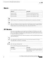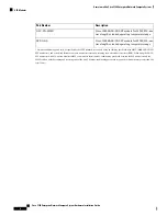
Before you begin
• Connect the chassis to the earth ground; the ground wire must be installed in accordance with local
electrical safety standards.
• For grounding, use size 14 AWG copper wire and the ground lug provided in the accessory kit.
Step 1
Strip one end of the ground wire to the length required for the ground lug.
Step 2
Crimp the ground wire to the ground lug using a crimp tool of the appropriate size.
Step 3
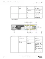
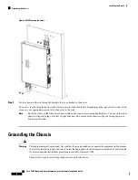
Attach the ground lug to the chassis as shown in the figure. Use the screws provided along with the ground lug to attach
the lug to the device.
Figure 9: Chassis Ground Connection on the Device
Powering On the Server
Step 1
Attach the power cord to the power supply unit in the server and then attach the other end of the power cord to the
grounded power outlet.
Step 2
Wait for approximately three minutes.
Step 3
Verify the power status of the system by looking at the system power status LED. The power status LED blinks in amber
color during initial boot up and in solid amber when the system reaches the standby power mode.
Initial Server Setup
Local Connection Procedure
1.
Ensure that the device is powered on.
2.
Connect serial console port on the front panel of the device.
3.
When you see the prompt, you can press F2 to get into the setup (BIOS) to change some settings.
4.
After you have performed the required configuration, save the setup and continue to boot.
Remote Connection Procedure
1.
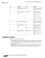
Plug in your terminal server to the Serial port (Refer to Front panel of Chassis).
2.
Telnet into the console and perform the necessary configuration using corresponding commands.
Cisco 5100 Enterprise Network Compute System Hardware Installation Guide
19
Installing the Device
Powering On the Server

