background image

C H A P T E R

1

Overview of the Cisco 5100 Enterprise Network
Compute System

The Cisco 5100 Enterprise Network Compute System (ENCS) combines routing, switching, storage, processing,
and a host of other computing and networking activities into a compact one Rack Unit (RU) box. This
high-performance unit achieves this goal by providing the infrastructure to deploy virtualized network functions
while at the same time acting as a server that addresses processing, workload, and storage challenges.

Cisco 5100 Series Enterprise Network Compute System Chassis, on page 1

Hardware Features - Standard, on page 2

Hardware Features, on page 6

Models, on page 7

SFP Modules, on page 7

Cisco 5100 Series Enterprise Network Compute System Chassis

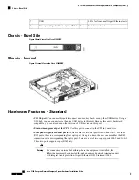
Chassis - Front Panel

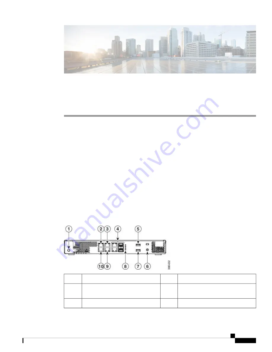
Figure 1: Front Panel of the Cisco 5100 ENCS

Ethernet management port

2

Power on/standby switch

1.

Front panel Gigabit Ethernet combo ports
GE0-0 and GE0-1

4

Front panel Gigabit Ethernet ports GE0-2

3

Ground

6

USB

5

Cisco 5100 Enterprise Network Compute System Hardware Installation Guide

1

Summary of Contents for 5100

Page 1: ... Compute System Hardware Installation Guide First Published 2017 09 25 Americas Headquarters Cisco Systems Inc 170 West Tasman Drive San Jose CA 95134 1706 USA http www cisco com Tel 408 526 4000 800 553 NETS 6387 Fax 408 527 0883 ...

Page 2: ...nna Increase the separation between the equipment and receiver Connect the equipment into an outlet on a circuit different from that to which the receiver is connected Consult the dealer or an experienced radio TV technician for help Modifications to this product not authorized by Cisco could void the FCC approval and negate your authority to operate the product The Cisco implementation of TCP hea...

Page 3: ...s Bezel Side 2 Chassis Internal 2 Hardware Features Standard 2 Hardware Features 6 Models 7 SFP Modules 7 Preparing for Installation 9 C H A P T E R 2 Safety Recommendations and Warnings 9 Safety with Electricity 10 Site Requirements 11 Mounting Requirements 12 Power Guidelines and Requirements 13 Network Cabling Specification 13 Required Tools and Equipment 13 Installing the Device 15 C H A P T E...

Page 4: ...wering On the Server 19 Initial Server Setup 19 Installing and Upgrading Field Replaceable Units 21 C H A P T E R 4 Removing and Replacing the Chassis Cover 21 Installing a DIMM 22 Removing a DIMM 24 Upgrading the M 2 Storage Module 25 Cisco 5100 Enterprise Network Compute System Hardware Installation Guide iv Contents ...

Page 5: ...umentation Cisco Enterprise Network Function Virtualization Infrastructure Software NFVIS Configuration Guide API Reference for Cisco Enterprise Network Function Virtualization Infrastructure Software Obtaining Documentation and Submitting a Service Request For information on obtaining documentation using the Cisco Bug Search Tool BST submitting a service request and gathering additional informati...

Page 6: ...Cisco 5100 Enterprise Network Compute System Hardware Installation Guide vi Preface Obtaining Documentation and Submitting a Service Request ...

Page 7: ...acting as a server that addresses processing workload and storage challenges Cisco 5100 Series Enterprise Network Compute System Chassis on page 1 Hardware Features Standard on page 2 Hardware Features on page 6 Models on page 7 SFP Modules on page 7 Cisco5100SeriesEnterpriseNetworkComputeSystemChassis Chassis Front Panel Figure 1 Front Panel of the Cisco 5100 ENCS Ethernet management port 2 Power...

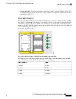
Page 8: ...this port to connect to the CPU in your device Front panel Gigabit Ethernet ports There are a set of two dual ports GE0 0 and GE0 1 For those RJ45 ports there is a corresponding fiber optic port At a given time the user can use either the RJ45 connection or the corresponding fiber optic port There are a set of two copper ports GE0 2 and GE0 3 Those two ports support copper RJ45 only For connection...

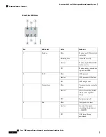
Page 9: ...st set of ports and the last two LEDs are for the second set of ports If both RJ45 and fiber optic ports are enabled when the system boots the fiber optic port is used and the RJ45 port is disabled Figure 4 LEDs for Gigabit Ethernet Ports The LEDs labeled EN indicates whether the corresponding ports are enabled The frequency of the blinks of the LEDs labeled S shows the speed of the corresponding ...

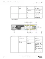
Page 10: ...with failure Amber SSD not present Off Temperature in acceptable range Blue Temperature 3 One or more temperature are not in acceptable range Amber Device power off Off Fan speed is correct Blue Fan 4 Incorrect fan speed exceeding the tolerance 500RPM Amber FAN is not being monitored Off Cisco 5100 Enterprise Network Compute System Hardware Installation Guide 4 Overview of the Cisco 5100 Enterpris...

Page 11: ...us Behavior Color LED Label No AMD power up Green System Boot LED 1 AMD power down Amber Link Green AMD Management port Speed LED 2 Green Blinking blink frequency indicates port speed 1 blink 10Mbps link speed 2 blinks 100Mbps link speed 3 blinks 1000Mbps link speed Blinking green Cisco 5100 Enterprise Network Compute System Hardware Installation Guide 5 Overview of the Cisco 5100 Enterprise Netwo...

Page 12: ...ED 7 Hardware Features The following are the units of Cisco 5100 ENCS M 2 storage module This is a high capacity storage component on the motherboard The OS is installable in this module The storage capacity of this module is upgradeable The different storage capacities that are currently available for this module are 64GB 200GB and 400GB Other storage capacities might be made available in the fut...

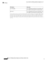
Page 13: ...es in Cisco ENCS 5100 The switch Gigabit Ethernet SFP and SFP modules provide copper or optical connections to other devices These modules are hot swappable and provide the uplink interfaces The SFP modules have fiber optic LC connectors or RJ 45 copper connectors Use only supported SFP modules on the switch Each module has an internal serial EEPROM that is encoded with security information If non...

Page 14: ...nsceivers and a short link distance can cause transceiver saturation resulting in an elevated bit error rate BER When using the LX LH SFP transceiver with 62 5 micron diameter MMF you must also install a mode conditioning patch cord between the SFP transceiver and the MMF cable on both the sending and receiving ends of the link The mode conditioning patch cord is required for link distances greate...

Page 15: ...warning symbol means danger You are in a situation that could cause bodily injury Before you work on any equipment be aware of the hazards involved with electrical circuitry and be familiar with standard practices for preventing accidents Use the statement number provided at the end of each warning to locate its translation in the translated safety warnings that accompanied this device Statement 1...

Page 16: ...quickly turn off the power Disconnect all power before doing the following Installing or removing a chassis Working near power supplies Look carefully for possible hazards in your work area such as moist floors ungrounded power extension cables frayed power cords and missing safety grounds Do not work alone if hazardous conditions exist Never assume that power is disconnected from a circuit Always...

Page 17: ...0 megohms Mohm Caution Site Requirements Follow the general precautions listed below when installing or working with your device Do not block cooling vents Route system cables and the power supply cable and plug so that they cannot be stepped on or tripped over Be sure that nothing else rests on your system component cables or power cable If you turn off your system wait at least 30 seconds before...

Page 18: ...th 10 0 inches 25 4 cm Depth 6 6 lbs 2 99 kg Weight To place the system in a proper location it is necessary to know the dimensions of the device s chassis The Cisco 5100 ENCS can be placed on a desktop or installed in a rack The mounting ears for the device are designed for 12 24 UNC screws The location of your device and the layout of your equipment rack or wiring room are extremely important co...

Page 19: ...r cord Network Cabling Specification Ethernet cables for RJ45 ports Serial or console cables used to connect devices like routers Shielded USB cables with properly terminated shields for the USB port Required Tools and Equipment You will need the following equipment to install the device and its equipment ESD preventive cord and wrist strap Phillips screwdrivers small 3 16 in 4 to 5 mm and medium ...

Page 20: ...Cisco 5100 Enterprise Network Compute System Hardware Installation Guide 14 Preparing for Installation Required Tools and Equipment ...

Page 21: ...tal damage Installing the Cisco 5100 ENCS If not already installed the DIMMs and the M 2 storage module must be installed before rack mounting or wall mounting the chassis Only trained and qualified personnel should be allowed to install replace or service this equipment Statement 1030 Warning Rack Mounting the Chassis The Cisco 5100 ENCS can be installed in 19 inch 48 26 cm racks Use the standard...

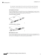
Page 22: ...e Use the screws provided with the mounting kit to attach the screws to the device Figure 5 Bracket Installation for Front Mounting Figure 6 Bracket Installation for Back Mounting Mounting the device in a Rack After you attach the brackets to the device install the chassis on the rack as shown in following figures You need two screws to attach each bracket to the rack Total four screws are require...

Page 23: ... small holes do not line up with the rack holes you must raise or lower the brackets to the next rack hole Tip Wall Mounting the Chassis These are the steps to wall mount the chassis Step 1 Attach the brackets to the device using the screws provided with the mounting kit Two screws should be used to attach each bracket to the chassis as shown in the following figure Cisco 5100 Enterprise Network C...

Page 24: ...ts going out in left or right direction Do not mount the chassis with ports facing upward or downward direction Note Grounding the Chassis This equipment must be grounded Never defeat the ground conductor or operate the equipment in the absence of a suitably installed ground conductor Contact the appropriate electrical inspection authority or an electrician if you are uncertain that suitable groun...

Page 25: ...the grounded power outlet Step 2 Wait for approximately three minutes Step 3 Verify the power status of the system by looking at the system power status LED The power status LED blinks in amber color during initial boot up and in solid amber when the system reaches the standby power mode Initial Server Setup Local Connection Procedure 1 Ensure that the device is powered on 2 Connect serial console...

Page 26: ...Cisco 5100 Enterprise Network Compute System Hardware Installation Guide 20 Installing the Device Initial Server Setup ...

Page 27: ...s equipment Statement 1030 Warning These are the steps to remove the chassis cover Step 1 Confirm that the chassis is turned off and disconnected from the power supply or power supplies Step 2 Place the chassis on a flat surface Step 3 Remove the screws at top of the chassis cover Step 4 Remove the screws at the sides of the device as shown in the following figure Figure 10 Removing the Chassis Co...

Page 28: ...Ms have a polarization notch on the connecting edge to prevent incorrect insertion Figure 11 DIMM Showing Polarization Notch These are the steps to install a DIMM Step 1 Remove the chassis cover Step 2 Locate the DIMM module on the device Cisco 5100 Enterprise Network Compute System Hardware Installation Guide 22 Installing and Upgrading Field Replaceable Units Installing a DIMM ...

Page 29: ...osition Step 4 Orient the DIMM so that the polarization notch lines up with the polarization key on the connector Step 5 Insert the DIMM into the connector Cisco 5100 Enterprise Network Compute System Hardware Installation Guide 23 Installing and Upgrading Field Replaceable Units Installing a DIMM ...

Page 30: ...ection to identify and locate the DIMM module Step 3 Pull the latches away from the DIMM at both ends to lift the DIMM slightly Pull the DIMM out of the socket Figure 14 Removing a DIMM Step 4 Place the DIMM in an antistatic bag to protect it from ESD damage Step 5 Replace the chassis cover Cisco 5100 Enterprise Network Compute System Hardware Installation Guide 24 Installing and Upgrading Field R...

Page 31: ...assis Internal on page 2 to identify and locate the module Step 3 Unscrew the screw that secures the old M 2 storage module and then remove the old M 2 storage module Step 4 Plug in the new M 2 storage module in the same location and secure it with the screw Figure 15 Upgrading the M 2 Storage Module Step 5 Replace the chassis cover Cisco 5100 Enterprise Network Compute System Hardware Installatio...

Page 32: ...Cisco 5100 Enterprise Network Compute System Hardware Installation Guide 26 Installing and Upgrading Field Replaceable Units Upgrading the M 2 Storage Module ...

Reviews: