3-3
Cisco ASA 5500 Series Hardware Installation Guide
78-17374-01
Chapter 3 ASA 5510, ASA 5520, ASA 5540, and ASA 5550
Product Overview
For more information about the Management port, see the
management only
command
in the
Cisco Security Appliance Command Reference.
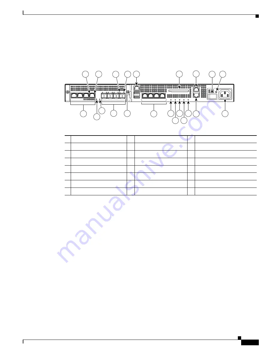
The ASA 5550 has a fixed configuration with an embedded 4GE slot as shown in
.
Figure 3-3
Rear Panel LEDs and Ports for the ASA 5550
1
RJ-45 ports
1
1.
GigabitEthernet ports, from right to left, GigabitEthernet 0/0, GigabitEthernet 1/0, GigabitEthernet 1/2, and
GigabitEthernet 1/3
9
USB 2.0 interfaces
2
2.
Not supported at this time.
17
AUX port
2
RJ-45 Link LED
10
Management port
3
3.
The management 0/0 interface is a Fast Ethernet interface designed for management traffic only.
18
External CompactFlash slot
3
RJ-45 Speed LED
11
Network interfaces
4
4.
GigabitEthernet interfaces, from right to left, GigabitEthernet 0/0, GigabitEthernet 0/1, GigabitEthernet 0/2, and
GigabitEthernet 0/3.
19
Serial Console port
4
Power LED
12
Power indicator LED
20
Power switch
5
Status LED
13
Status indicator LED
21
Power indicator LED
6
SFP ports
5
5.
SFP ports, from right to left, GigabitEthernet 0/0, GigabitEthernet 1/0, GigabitEthernet 1/2, and GigabitEthernet 1/3
14
Active LED
22
Power connector
7
SFP Link LED
15
VPN LED
8
SFP Speed LED
16
Flash LED
153642
LINK SPD
2
LINK SPD
1
LINK SPD
0
LINK SPD
3
MGMT
USB2
USB1
FLASH
CONSOLE
AU
X
PO
WER
ST
AT
US
FLASH
10
13
18
19
20
21
15
17
22
11
12 14 16
VPN
A
C
TIVE
P
W
R
LNK
SPD
0
1
2
3
9
4
1
6
5
2
3
7
8


