4-5
Cisco ASA 5580 Series Adaptive Security Appliance Hardware Installation Guide
OL-12920-01
Chapter 4 Maintenance and Upgrade Procedures
Removing and Installing the Interface Cards
This section includes the following topics:
•
Removing the Interface Cards, page 4-5
•
Installing an Interface Cards, page 4-6
Caution
To prevent damage to the ASA 5580 or the expansion cards, power down the ASA 5580 and remove all
AC power cables before removing or installing expansion cards.
Removing the Interface Cards
To remove the interface cards, perform the following steps:
Step 1
Power off the ASA
Step 2
Remove the power cables from the ASA.
Step 3
If rack-mounted, extend the ASA from the rack.
Step 4
Make sure the ASA is in an ESD-controlled environment.
For more information, see the
“Preventing Electrostatic Discharge Damage” section on page 2-2.
Step 5
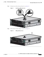
Remove the chassis cover.
For more information, see the
“Removing the Chassis Cover” section on page 4-2
.
Step 6
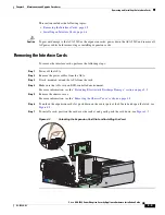
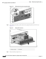
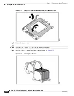
To unlock the expansion card slot, push down on the center part of the blue tab and open the latch, see
Figure 4-3
.
Step 7
To install a card, position the card over the socket, and gently push the card down, see
Figure 4-3
.
Figure 4-3
Unlocking the Expansion Card Slot and Installing the Card
250204
3
4
5
6
7
8
9
PCI-E
x4
PCI-E
x8
PCI-E x4
PCI-E
x8
PCI-E
x4
P
UID
PS2

