3
Introduction
OL-2186-01
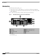
Introduction
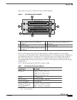
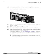
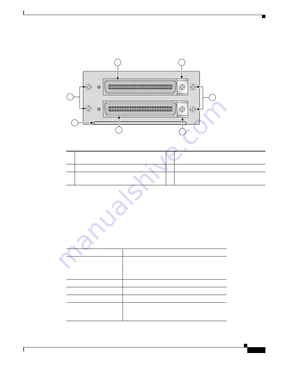
Figure 2 shows a close-up of the DSL interface module faceplate.
Figure 2
DSL Interface Module Faceplate
The Cisco 6015 chassis follows the FCC part 68 industry standard convention for Tip and Ring
connections on the twisted pairs of the 50-pin Champ connector. The Champ connectors are pinned out
to accommodate quad-port or octal-port xTU-C line cards. If you are not currently using octal-port
xTU-C line cards but plan to in the future, Cisco recommends that you use Champ cables that can
accommodate higher density line cards. Refer to the Cisco 6015 Hardware Installation Guide for port
mapping tables.
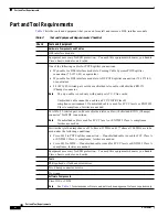
lists the specifications for the DSL interface module.
1
50-pin Champ connector for DSL slots 1
through 3
4
50-pin Champ connector for DSL slots 4
through 6
2
Cable tie-downs
5
Extraction handle
3
Screws to secure the DSL interface module to
the chassis
42373
DSL SLOTS 4–6
DSL SLOTS 1–3
2
1
5
2
3
4
3
Table 1
DSL Interface Module Specifications
Specification
Description
Dimensions
Height: 1.375 in. (3.493 cm)
Depth: 9.375 in. (23.813 cm)
Width: 3.375 in. (8.573 cm)
Weight
0.71 lb (0.32 kg)
Data connectors
Two 50-pin Champ connectors
Power consumption
Not applicable.
Minimum software and
network management
requirement
Cisco IOS—Release 12.1(4)DA
CDM
1
—Release 3.2 (optional)
1.
CDM = Cisco DSL Manager

