15
Cisco 6100 Thermal Upgrade Kit Installation Procedures
78-10158-01
Installing the Cisco 6100 Thermal Upgrade Kit
Disconnect the Cisco 6100 Power Connections
To disconnect the Cisco 6100 power connections, complete the following steps:
Note
If you do not have 12 AWG wire installed, you will replace these wires with a larger gauge
wire later in the procedures.
Step 1
Use a socket driver or a Phillips-head screwdriver to remove the clear cover over the Cisco 6100
power connections.
Step 2
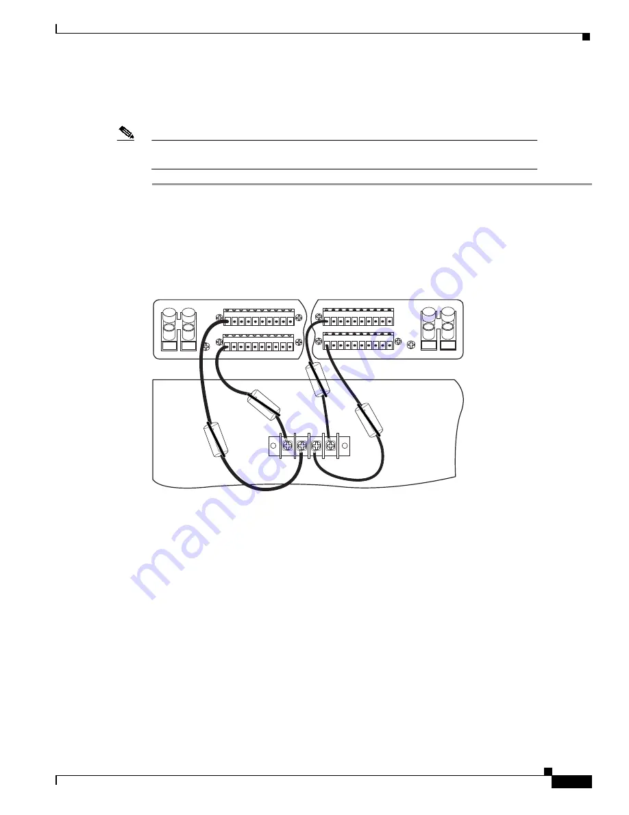
Disconnect the wires connecting the Cisco 6100 chassis to the fuse and alarm panel (POS RTN and
NEG DC connections) as shown in Figure 2 (dual-power feed) and Figure 3 (single-power feed).
These wires will be replaced with a larger gauge wire later in the procedures.
Figure 2
Power Return Connections for the Cisco 6100—Dual-Power Feed
1 2 3 4 5 6 7 8 9 10
Cisco 6100/6130
P13
-48V_A
-48RTN
-48V_B
-48RTN
NEG
NEG
POS
POS
NEG DC
NEG DC
POS RTN
POS RTN
B
A
1 2 3 4 5 6 7 8 9 10
1 2 3 4 5 6 7 8 9 10
1 2 3 4 5 6 7 8 9 10
18393


