29
Cisco 6100 Thermal Upgrade Kit Installation Procedures
78-10158-01
Installing the Cisco 6100 Thermal Upgrade Kit
Step 6
Use a Phillips-head screwdriver to attach a wire to the –48V_B power input connection on the
Cisco 6100 (P13).
Step 7
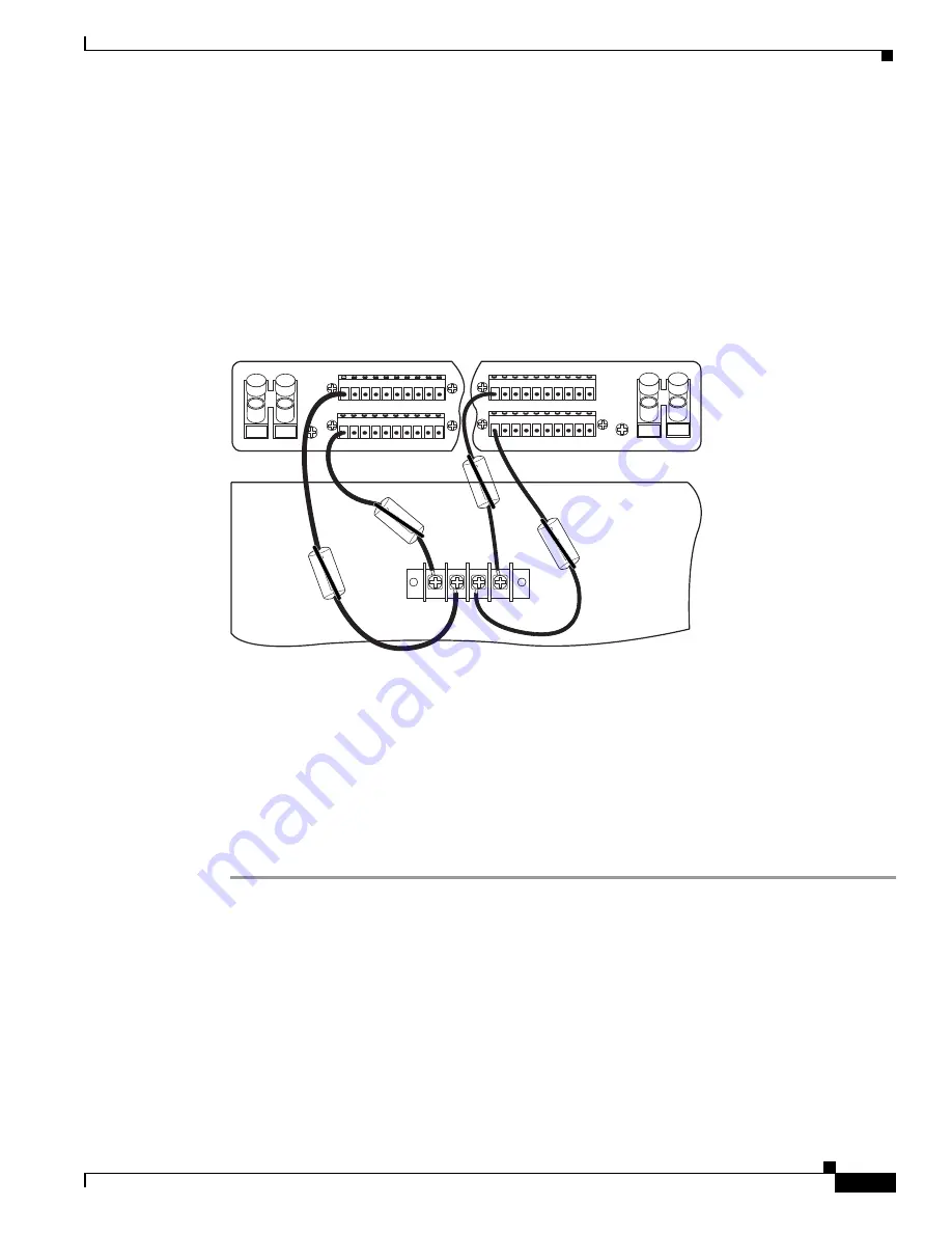
Loop the wire through the ferrite as shown in Figure 12.
Step 8
Attach the wire to a fuse and alarm panel NEG DC connector.
Step 9
Measure enough wire (12 AWG black and red copper solid or stranded wire) to connect each of the
Cisco 6100 power return connections to the fuse and alarm panel.
Figure 13 shows the Cisco 6100 power return connections wired to the fuse and alarm panel for a
dual-power feed.
Figure 13
Power Return Connections for the Cisco 6100—Dual-Power Feed
Step 10
Use a wire stripper to remove the casing from both ends of the wires.
Step 11
Use a Phillips-head screwdriver to attach a wire to a –48V power return connection (–48RTN) on the
Cisco 6100 (P13).
Step 12
Loop the wire through the ferrite as shown in Figure 12.
Step 13
Attach the wire to a fuse and alarm panel POS (positive) RTN connector.
Step 14
Repeat Steps 9 through 13 for the remaining –48V power return connection (–48RTN).
Step 15
Use a socket driver or a Phillips-head screwdriver to attach the clear cover over the Cisco 6100
power connections.
1 2 3 4 5 6 7 8 9 10
Cisco 6100/6130
P13
-48V_A
-48RTN
-48V_B
-48RTN
NEG
NEG
POS
POS
NEG DC
NEG DC
POS RTN
POS RTN
B
A
1 2 3 4 5 6 7 8 9 10
1 2 3 4 5 6 7 8 9 10
1 2 3 4 5 6 7 8 9 10
18393


