35
Cisco 6100 Thermal Upgrade Kit Installation Procedures
78-10158-01
Installing the Cisco 6100 Thermal Upgrade Kit
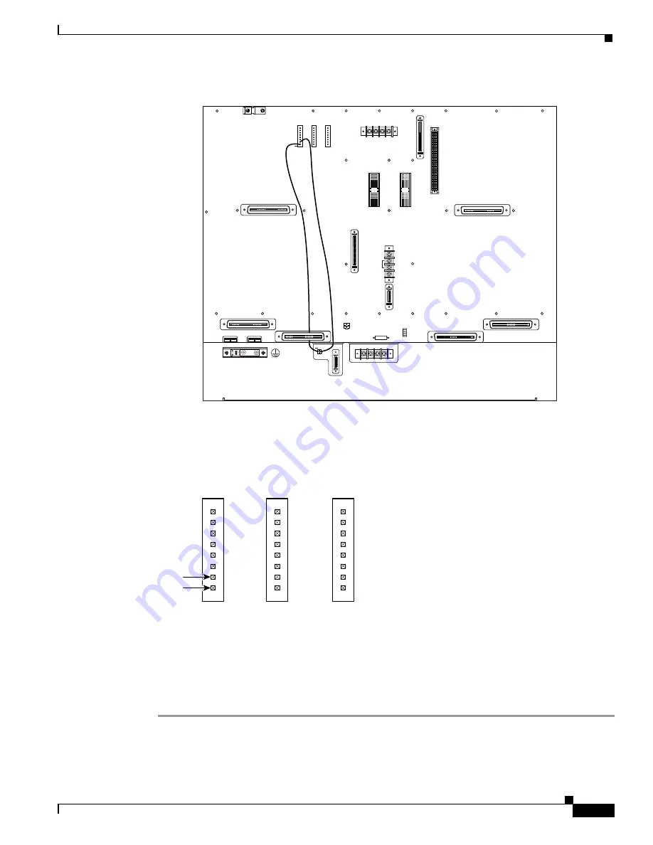
Figure 19
Wiring the Fan Tray Alarm Contacts
See Figure 20 for a close view of the alarm contact pinouts. For pinout descriptions, see the Cisco 6100
with NI-1 Direct Connect Installation Guide.
Figure 20
Alarm Contact Pinouts—Close-up
Step 2
Use a wire stripper to remove the casing from both ends of the wires.
Step 3
Wire P2 on the backplane of the fan tray to P14 (pin 7) on the backplane of the Cisco 6100 to connect
the Fan Alarm+ contact. Use a wire wrapping tool to attach the wire to the contacts.
Step 4
Wire P2 on the backplane of the fan tray to P15 (pin 8) on the backplane of the Cisco 6100 to connect
the Fan Alarm– contact. Use a wire wrapping tool to attach the wire to the contacts.
Cisco
6100
32211
P2
J1
Fan tray
+
+
FAN
P2
J1
-48V
A
RT
N
-48VB
RT
N
1
2
1
2
P14
P17
P15
E2A
VISUAL
AUDIBLE
FA
N
ALARM
MIN
MAJ
CRIT
AC
O
MIN
MAJ
CRIT
AC
O
MIN
MAJ
CRIT
P16
SHORTING
JUMPER
XDSL
PROTECTION
BUS
SLOT 20 CONFIG.
ON
OFF
SLOT 38 CONFIG.
ON
OFF
ANALOG TEST I/F
RING
TIP
P18
-48V_B
-48R
TN
-48V_A
-48R
TN
P13
-48R
TN
P19
GRN JUMPER
CHASSIS
GND
LOGIC
GND
MODEM
POOL
A
OUT
J45
J48
P3
P9
J39
J42
MODEM
POOL
B
OUT
J46
J43
J44
J41
J40
J47
SW2
SW1
P14
P17
P15
E2A
VISUAL
AUDIBLE
FA
N
ALARM
MIN
MAJ
CRIT
AC
O
MIN
MAJ
CRIT
AC
O
MIN
MAJ
CRIT
31721
Pin 7
Pin 8


