1-21
Cisco 7100 Series VPN Router Installation and Configuration Guide
78-6341-03
Chapter 1 Overview
Cisco 7140 Series Overview
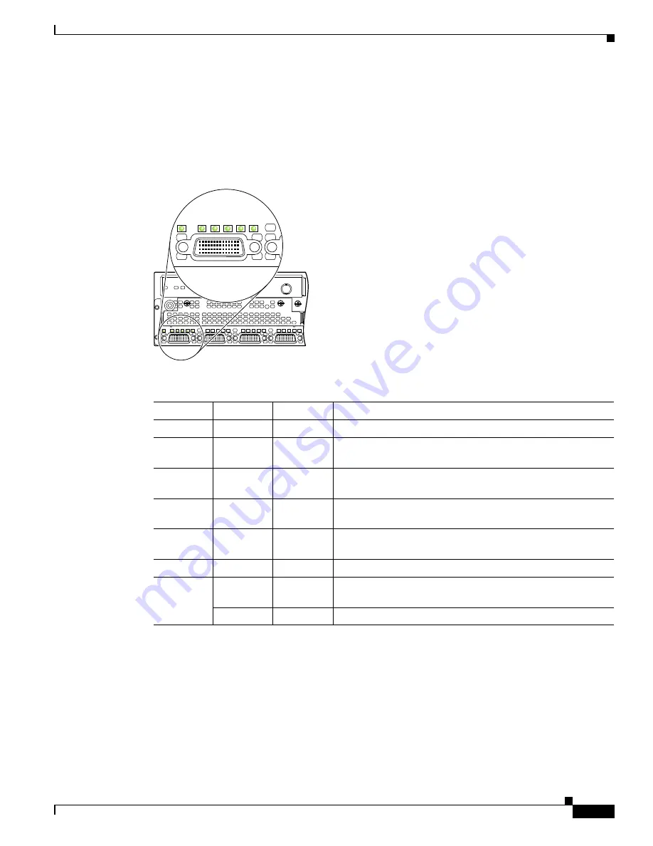
The Cisco 7140-8T WAN ports have one enabled (EN) LED and five status LEDs (each of the eight ports
has a set of status LEDs). After system initialization, the enabled LED goes on to indicate that all ports
have been enabled for operation. If the initialization fails for any reason, the enabled LED will not go
on. The LEDs are shown in
Figure 1-24
and described in
Table 1-8
.
Figure 1-24 Cisco 7140-8T WAN Port LEDs
Table 1-8
Cisco 7140-8T LED Descriptions
LED Label
Color
State
Function
EN
Green
On
Indicates ports are ready.
TD
Green
On
DTE—Transmit data out.
DCE—Transmit data in.
TC
Green
On
DTE—Transmit clock in.
DCE—Transmit clock in (TxCE).
RD
Green
On
DTE—Receive data in.
DCE—Receive data out.
RC
Green
On
DTE—Receive clock in.
DCE—Receive clock out.
Loopback/
Green
On
Indicates DTR
1
, DSR
2
, RTS
3
, CTS
4
, or DCD
5
is active.
1.
DTR = Data Terminal Ready.
2.
DSR = Data Set Ready.
3.
RTS = Request To Send.
4.
CTS = Clear To Send.
5.
DCD = Data Carrier Detect.
Carrier
Detect
Green
Flushing
Indicates RTS, CTS, or DCD is sending and receiving data in
half-duplex mode.
Yellow
On
Indicates local loop or internal loop active.
TD
TC
RD
RC
LB
CD
TD
TC
RD
RC
LB
CD
EN
TC
TD
RD
RC
LB
CD
5
I
TC
RD
RC
LB
CD
TD
18485
TC
TD
RD
RC
LB
CD
EN
LEDs


