1-30
Cisco 7100 Series VPN Router Installation and Configuration Guide
78-6341-03
Chapter 1 Overview
Functional Overview
Functional Overview
The following sections provide a functional overview of Cisco 7100 series VPN routers to help you
become familiar with the capabilities of the router:
•
Chassis Slot and Logical Interface Numbering, page 1-30
•
Online Insertion and Removal, page 1-33
•
Peripheral Component Interconnect Buses, page 1-33
•
Network Processor Card, page 1-34
•
System LEDs and Reset Button, page 1-38
•
Environmental Monitoring and Reporting Functions, page 1-39
Chassis Slot and Logical Interface Numbering
In Cisco 7100 series VPN routers, the slot number is the location in the chassis where the interface
resides and the port number is the physical port associated with that slot. Cisco 7100 series router slots
are numbered 0 through 5. Interfaces in the Cisco IOS software are identified by a type, slot number, and
port number. The number of physical ports depends on the type of modular port adapter or fixed
interface. For example, in a Cisco 7120-4T1, serial 1/0 indicates port 0 on the fixed serial interface in
slot 1. (See
Figure 1-5
.)
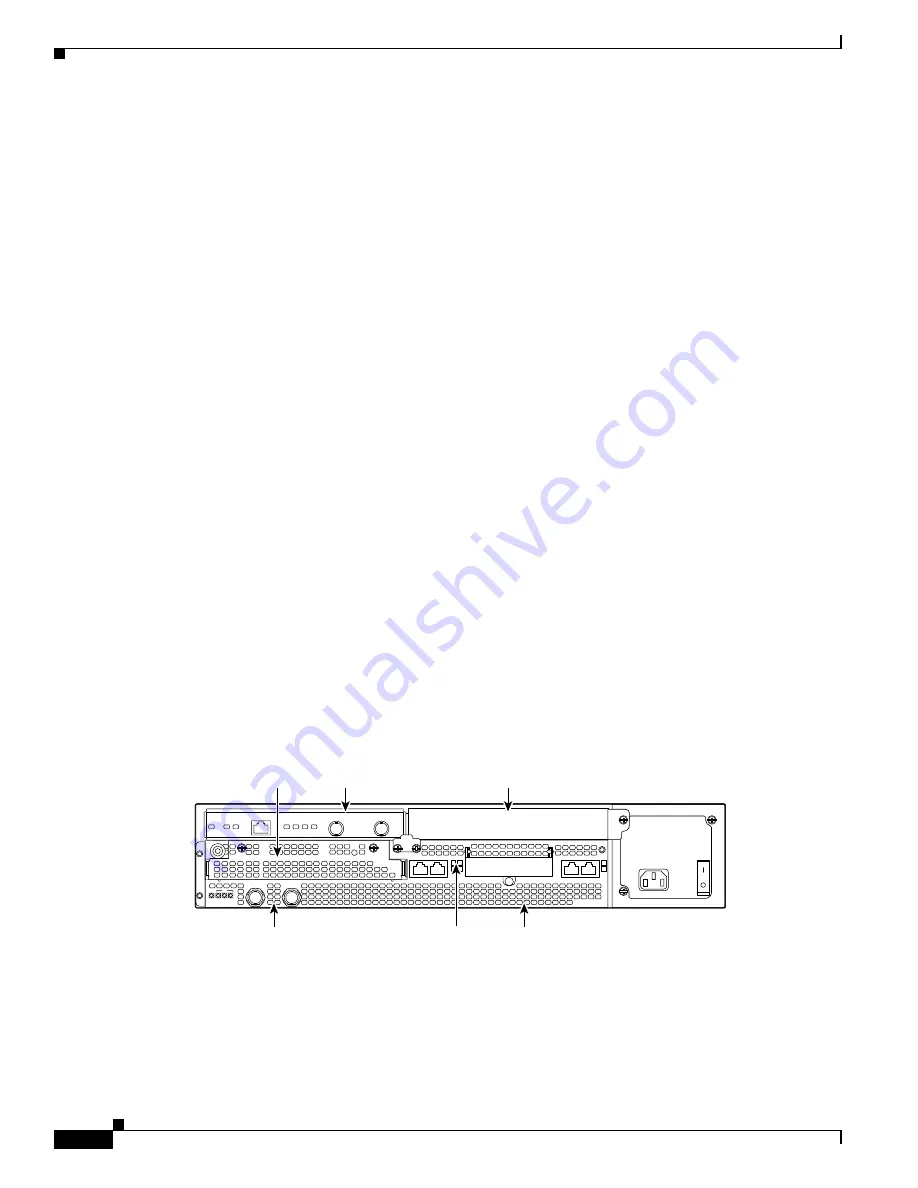
Slots in the Cisco 7120 series are numbered as follows and are shown in
Figure 1-31
:
•
Slot 0—Fixed LAN (Ethernet) interface
•
Slot 1—Fixed WAN (serial) interface
•
Slot 2—Not used
•
Slot 3—Modular port adapter
•
Slot 4—Not used
•
Slot 5—Integrated Service Module
Figure 1-31 Port Adapter Slot Numbering—Cisco 7120 Series
Slots in the Cisco 7140 series are numbered as follows and are shown in
Figure 1-32
:
•
Slot 0—Fixed LAN (Ethernet) interface
•
Slot 1—Fixed WAN (serial) interface
•
Slot 2—Fixed WAN (serial) interface
SLOT 0
SLOT 1
0
2
FE 0 / 0
FE
AUX
7120 - AE3
RX
TX
E3
RX
EN
CEL CAR ALM
5
I
CONS
ACT
0 / 1
ACT
LNK
0
LNK
1
PWR
SYS
RDY
Slot 1
Slot 0
Slot 3
Slot 4
Slot 5
18498
Slot 2


