4-4
Cisco 7304 Network Service Engine Installation and Configuration
OL-3967-01
Chapter 4 Removing and Installing the NSE
Removing the Network Services Engine
Removing the Network Services Engine
Caution
Two NSE-100s, two NSE-150s, or two NPE-G100 configurations are supported on the Cisco 7304
router. You cannot use different processors in the same Cisco 7304 router at the same time.
To remove an NSE from a Cisco 7304 router, complete the following steps:
Step 1
Power down the router and disconnect the input power cable. (Refer to the
“Powering Down the Router
and Disconnecting Input Power” section on page 4-2
.)
Step 2
Attach an ESD-preventive wrist strap between you and an unfinished chassis surface.
Step 3
Remove any GBIC module, SFP module, Fast Ethernet Console port, auxiliary port, or any other cables.
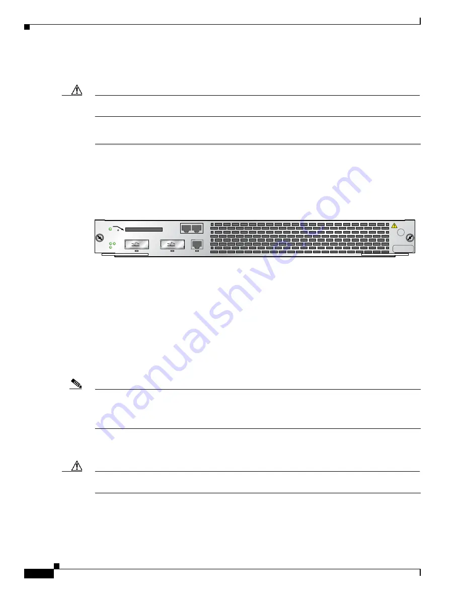
Figure 4-1
Cisco 7304 NSE-100 Captive Installation Screws and Levers
Step 4
Using a number 2 Phillips or a 3/16-inch flat-blade screwdriver, loosen the two captive installation
screws on the faceplate of the network services engine. (See
Figure 4-1
.)
If the router is not installed in a standard 19-inch, 4-post or 2-post rack, skip to
Step 8
. If the router is
installed in a rack, determine if any permanent rack fixtures, such as a power strip, are obstructing access
to the front of the router. If a rack fixture is obstructing access to the router, proceed with
Step 5
.
Step 5
Using a 3/16-inch flat-blade screwdriver, loosen the screws that secure the router to the front mounting
strips of the rack.
Step 6
Position at least one person in front of the rack to support the front underside of the router.
Step 7
From the front of the rack, carefully push the front of the router out of the rack until there is enough
clearance to remove the network services engine.
Note
If you have difficulty removing or installing a processor in the lowest slot of a Cisco 7304 router that is
rack-mounted, remove the line cards, port adapter carrier cards, and processor from the chassis and reinstall
them. Install a processor engine in the lowest slot first, then populate the slots above it, in a bottom-to-top
order.
Step 8
Pull the network services engine locking levers outwards and carefully pull the network services engine
from its chassis slot.
Caution
Handle the network services engine by the carrier edges only; never touch the printed circuit board
components or connector pins.
57707
THIS ASSEMBLY
CONTAINS
ELECTRO-STATIC
SENSITIVE DEVICES
CAUTION:
PRIMARY
DISK 0
7300-NSE-100
NETWORK SERVICES ENGINE 100
RESET
LINK
GE 0
RX
TX
LINK
GE 1
LINK
FE MANAGEMENT
PORT
AUX
CONSOLE
RX
TX
COMPACT FLASH
SECONDARY
SYSTEM-UP


