4-17
Cisco 7304 Network Service Engine Installation and Configuration
OL-3967-01
Chapter 4 Removing and Installing the NSE
Installing and Removing SFP Modules (NSE-150)
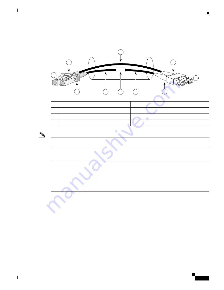
Attaching the Mode-Conditioning Patch Cord
Figure 4-11
Mode-Conditioning Patch Cord
Note
Figure 4-11
shows one type of mode-conditioning patch cord. For specifications, see the
“Mode-Conditioning Patch Cord Description” section on page 1-11
.
To use a mode-conditioning patch cord, follow these steps:
Step 1
Attach a patch cord to the GBIC module. (See
Figure 4-11
.)
Step 2
Attach the network ends of your patch cord to the appropriate 1000BASEX equipment in your building
cable plant.
Ensure that you connect the TX and RX ports on one end of the patch cord to the RX and TX ports
(respectively) on the other end. Connect TX to RX and RX to TX.
Installing and Removing SFP Modules (NSE-150)
The NSE-150 uses SFP modules to connect to copper and fiber-optic media types.
Before powering up the router, ensure all SFP module cabling is installed.
To see the SFP modules supported on the NSE-150, see the
“Gigabit Ethernet SFP Port and Cabling
Specifications” section on page 2-6
.
For instructions on installing and removing SFPs, see the
Cisco Small Form-Factor Pluggable Modules
Installation Notes
.
1
Gray color identifier
5
Single-mode bar
2
To GE interface
6
Offset
3
Blue color identifier
7
Beige color identifier
4
Multimode bar
8
To cable plant
/ /
/ /
/ /
TX
Offset
RX
84159
1
7
2
3
7
4
8
6
5
4


