R E V I E W D R A F T — C I S C O C O N F I D E N T I A L
3-7
Cisco 7500 Series Installation and Configuration Guide
OL-5008-03 B0
Chapter 3 Installing a Cisco 7500 Series Router
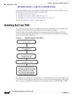
Installing the Cisco 7505
Cisco 7505 Installation Considerations
Before you install the Cisco 7505, decide where to install the router. If you intend to rack-mount the
router, proceed to the
“Rack-Mounting the Cisco 7505” section on page 3-7
. If you do not intend to
rack-mount the router, follow these steps to install the Cisco 7505 on a bench or tabletop:
Step 1
Make sure that your installation area is free of debris and dust.
Step 2
Make sure your path between the chassis and where you will place it is unobstructed.
Caution
To prevent damage to the chassis and components, never attempt to lift or tilt the chassis with the handles
on the interface processors. These handles are not designed to support the weight of the chassis.
Step 3
Carefully place the chassis on the tabletop or bench.
Step 4
On the chassis, ensure that all captive screws (on the processor modules, and so forth) are tightened and
the components are secure.
Step 5
For an AC-input power supply: push the cable retention clip away from the power receptacle and plug
in the power cable.
Step 6
For a DC-input power supply, proceed to the
“Connecting Power to the Cisco 7505 DC-Input Power
Supply” section on page 3-9
; otherwise, continue with Step 7.
Step 7
Secure the cable in the power supply receptacle by pushing the cable retention clip until it snaps into
place around the cable connector.
Step 8
Connect the opposite end of the power cable to an appropriate power source.
Caution
Do not turn on any power supplies until you are ready to power up the system. The interlock switch that
locks the power supply in the slot also turns on the system power.
Rack-Mounting the Cisco 7505
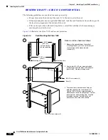
Before you begin the optional rack-mount installation, have the following tools and parts on hand:
•
Number 1 and number 2 Phillips screwdrivers
•
1/4-inch and 3/16-inch flat-blade screwdrivers
•
Tape measure
•
Level (optional)
•
Two chassis ears (rack brackets included with Cisco 7505)
•
Four M4 x 10-mm Phillips flat-head screws to secure the ears to the chassis (included)
•
Eight 10-32 x 3/8-inch slotted binderhead screws to secure the chassis ears to the mounting strips
(also called rails) in the rack
Warning
To prevent bodily injury when mounting or servicing this unit in a rack, you must take special
precautions to ensure that the system remains stable.

