R E V I E W D R A F T — C I S C O C O N F I D E N T I A L
3-14
Cisco 7500 Series Installation and Configuration Guide
OL-5008-03 B0
Chapter 3 Installing a Cisco 7500 Series Router
Installing the Cisco 7507 and Cisco 7507-MX
Cisco 7507 and Cisco 7507-MX Installation Considerations
Before you install the Cisco 7507 or Cisco 7507-MX, decide where to install the router.
Note
If you plan to rack-mount the router, refer to the publication Cisco 7000 and Cisco 7507 Rack-Mount Kit
Installation Instructions (Document Number 78-1058-xx or later), which shipped with the rack-mount
kit ACS-7000RMK=. If rack-mounting is not required, use the following procedure to install a
Cisco 7507 or Cisco 7507-MX on a bench or tabletop.
On the rear of the chassis, do the following:
Step 1
Check the ejector levers to ensure that each RSP and all interface processors are securely installed.
Step 2
Check the captive installation screws on each RSP and each interface processor, and tighten any that are
loose.
Step 3
Ensure that both power supply bays are empty.
Warning
Two people are required to lift the chassis. Grasp the chassis underneath the lower edge and lift with
both hands. To prevent injury, keep your back straight and lift with your legs, not your back. To prevent
damage to the chassis and components, never attempt to lift the chassis with the handles on the
power supplies or on the interface processors, or by the plastic panels on the front of the chassis.
These handles were not designed to support the weight of the chassis.
Step 4
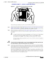
Two people are required to perform this step. With a person positioned at either side of the chassis, grasp
the bottom edge of the chassis with one hand near the front and the other near the back. Slowly lift the
chassis in unison. Avoid sudden twists or moves to prevent injury.
Caution
To prevent damage to the chassis and components, never attempt to lift or tilt the chassis with the handles
on the interface processors. These handles are not designed to support the weight of the chassis.
Step 5
Place the chassis on a bench or tabletop where the air intake vent on the front of the chassis (the bottom
front panel) is not drawing in exhaust air from other equipment.
Step 6
Ensure that you have at least 3 or 4 feet (0.91 to 1.22 m) of clearance around the rear of the chassis. You
will need this space to install the power supplies and perform maintenance on the chassis.
Step 7
Make sure that the area in which you install the chassis is free of debris and dust. Also make sure your
path to the area is unobstructed.
After you correctly position the chassis, proceed to the next section, “
Installing Cisco 7507 and Cisco
7507-MX Power Supplies
.”
Installing Cisco 7507 and Cisco 7507-MX Power Supplies
Your Cisco 7507 or Cisco 7507-MX was shipped with the power supplies removed. One power supply
is shipped as standard equipment; a second power supply is optional. Install power supplies only after
you have finally installed or rack-mounted the chassis.


