R E V I E W D R A F T — C I S C O C O N F I D E N T I A L
3-27
Cisco 7500 Series Installation and Configuration Guide
OL-5008-03 B0
Chapter 3 Installing a Cisco 7500 Series Router
Installing the Cisco 7513, Cisco 7513-MX, and Cisco 7576
Note
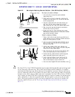
When you install the network interface cables, route the cables to and through the
cable-management bracket. If you are using very thin cables that slip through the bracket
openings, insert cable ties through the holes in the bracket and wrap them around the cables to
secure them.
It might be necessary to bundle longer cables to avoid tangling them. Do this at the
cable-management bracket or at the rack, but leave enough room to remove processor modules
and power supplies and to change cables as required. Do not block the power supply or chassis
intake air vents with cables. Verify that the cables do not interfere with removal and installation
of the blower module.
This completes the procedure for installing the cable-management bracket. Proceed to the next section,
“
Installing Cisco 7513, Cisco 7513-MX, and Cisco 7576 Power Supplies
.”
Installing Cisco 7513, Cisco 7513-MX, and Cisco 7576 Power Supplies
Your Cisco 7513, Cisco 7513-MX, or Cisco 7576 was shipped with the power supplies removed. The
Cisco 7513 and Cisco 7513-MX are shipped with one power supply as standard equipment; a second
power supply is optional equipment. When purchased new (not upgraded), the Cisco 7576 comes with
two AC-input power supplies as standard equipment. Install power supplies only after you have finally
installed or rack-mounted the chassis.
Based on the NFPA 70 National Electrical Code, you should use a 35-amp (A) overcurrent protector to
meet the requirement for the overcurrent protector size of 125 percent of the load current, which is
approximately 27A. An overcurrent protector rated for 30A can be used only if it has been listed by the
safety agency for operation at 100 percent of its rating.
Note
The following procedure applies to AC-input and DC-input power supplies, with specific differences
clearly noted. To prevent system problems, do not mix AC-input and DC-input power supplies in the
same chassis.
Follow this procedure to install a power supply in the Cisco 7513, Cisco 7513-MX, and Cisco 7576:
Step 1
If possible, turn off the circuit breaker to which you will connect power and tape the breaker switch in
the off position.
Step 2
Check the switch on the face of the power supply, and place it in the off (O) position. The interlock tab
should not extend out of the unit.
Step 3
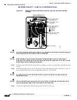
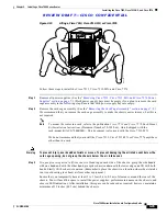
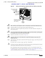
Hold the supply as shown in
Figure 3-17
and slide it into the power supply bay. Push the supply all the
way into the chassis until the sides are flush against the chassis frame. To prevent damaging the
backplane connector, do not jam the power supply into the bay.

