R E V I E W D R A F T — C I S C O C O N F I D E N T I A L
3-31
Cisco 7500 Series Installation and Configuration Guide
OL-5008-03 B0
Chapter 3 Installing a Cisco 7500 Series Router
Installing the Cisco 7513, Cisco 7513-MX, and Cisco 7576
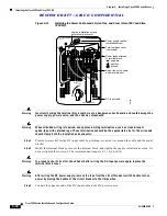
Figure 3-21
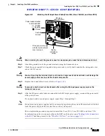
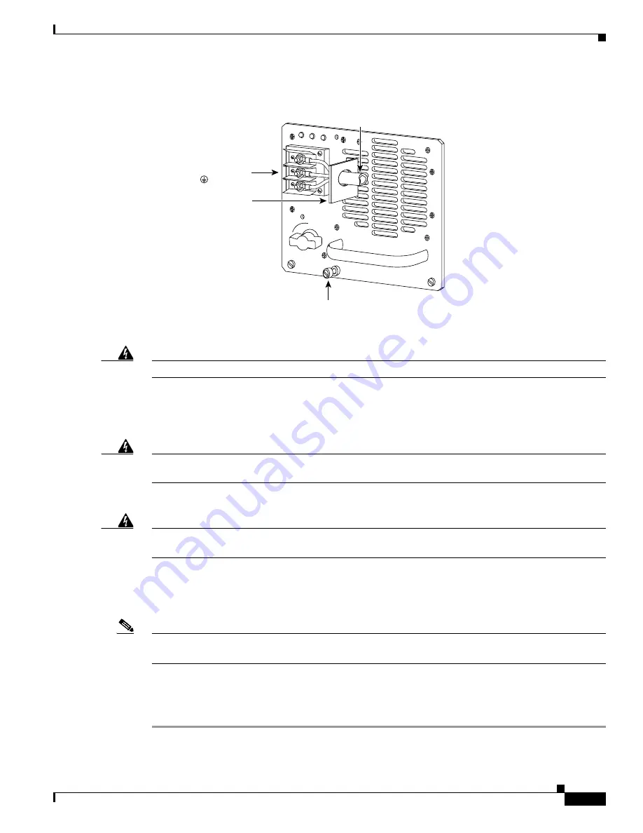
Attaching the DC-Input Power Cable (Cisco 7513, Cisco 7513-MX, and Cisco 7576)
Warning
When installing the unit, the ground connection must always be made first and disconnected last.
Step 6
Attach the ground wire to the ground terminals using the 8-mm nut driver.
Step 7
Check the power supply’s wiring and wiring color code to verify that it matches the wiring and color
code at the DC source.
Warning
Incorrectly wiring the terminal block could create a dangerous shock hazard and could damage the
power supply, power source, and the chassis components.
Step 8
Replace the terminal block cover. (Refer to
Figure 3-19
.)
Warning
To prevent a short-circuit or shock hazard after wiring the DC-input power supply, replace the
terminal block cover.
Step 9
After the DC power cable leads are connected to the DC-input power supply, reconnect the power cable
at the power source.
If you plan to add a second power supply, repeat Step 1 through Step 9.
Note
Do not turn on any power supplies until you are ready to power up the system. The interlock switch that
locks the power supply in the slot also turns on the system power.
This completes the procedures required to install the Cisco 7513, Cisco 7513-MX, and Cisco 7576.
For information on how to connect cables to the RSP, see the next section, “
Making Cable Connections
to the RSP
,”and then proceed to the
“What Do I Do Now?” section on page 3-33
.
122369
0
I
OK
OK
FAIL
DC
FAN OUTPUT
Power leads attached
to terminal block
(+) Positive
(–) Negative
( ) Ground
DC-input
cable (8-AWG)
Captive
installation
screw
DC-input power supply
with the terminal block
cover removed
Conduit
bracket

