6-7
Cisco 7500 Series Installation and Configuration Guide
OL-5008-03 B0
Chapter 6 Maintaining Your Cisco 7507 and Cisco 7507-MX Router
Maintenance Procedures for the Cisco 7507 and Cisco 7507-MX
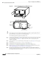
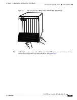
Figure 6-5
Removing the Cisco 7507 and Cisco 7507-MX Bottom Front Panel
.
Step 2
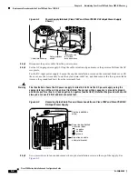
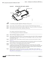
On the top front panel, use a number 1 Phillips or a 3/16-inch flat-blade screwdriver to loosen the two
captive screws at the bottom edge of the panel frame. (See
Figure 6-6
.)
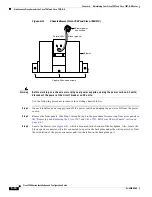
UPPER
POWER
LOWER
POWER
NORMAL
H3132


