6-12
Cisco 7500 Series Installation and Configuration Guide
OL-5008-03 B0
Chapter 6 Maintaining Your Cisco 7507 and Cisco 7507-MX Router
Maintenance Procedures for the Cisco 7507 and Cisco 7507-MX
Warning
Before working on a chassis or working near power supplies, unplug the power cord on AC units;
disconnect the power at the circuit breaker on DC units.
Removing and Replacing the Chassis Interface in the Cisco 7507 and Cisco 7507-MX
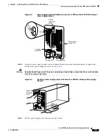
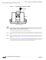
The chassis interface (CI) (shown in
Figure 6-9
) provides environmental monitoring and logic functions
for the Cisco 7507 and Cisco 7507-MX. The CI is a printed circuit board mounted to the noninterface
processor side (rear) of the backplane. The CI plugs directly into the backplane through the edge
connector on the CI and a connector on the rear of the backplane. The chassis interface ships as a spare
part as Product Number MAS-7500CI=. Replace the CI only if it fails.
Figure 6-9
7500 Series Chassis Interface
Use the following procedure to remove the CI:
Step 1
Turn off the system power switch and disconnect the power cable from the power source.
Step 2
Attach an ESD-preventive strap (your own or the one supplied with the FRU) between you and an
unpainted chassis surface.
Step 3
Remove the front panels. (See Step 1 through Step 6 in the procedure for removing front cover panels in
the
“Removing and Replacing the Cisco 7507 and Cisco 7507-MX Front Chassis Panels” section on
page 6-6
.)
Step 4
Locate the CI board on the rear of the backplane. (See
Figure 6-8
.)
Step 5
Carefully remove the CI from its backplane connector.
Note
If necessary, gently rock the CI from side to side very slightly to dislodge the pins from the backplane
connector.
Step 6
Place the CI in an antistatic bag.
This completes the CI removal procedure.
H2877
Chassis interface
Standoff
screw holes
Standoff
screw holes


