7-8
Cisco 7500 Series Installation and Configuration Guide
OL-5008-03 B0
Chapter 7 Maintaining Your Cisco 7513, Cisco 7513-MX, and Cisco 7576 Router
Maintenance Procedures for the Cisco 7513, Cisco 7513-MX, and Cisco 7576
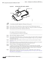
Figure 7-5
Location of the EEPROM Device on the Rear of the Card Cage (Cisco 7513 and
Cisco 7513-MX)
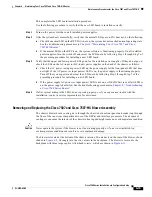
Figure 7-6
Location of the EEPROM Devices on the Rear of the Card Cage
(Cisco 7576)
Step 5
Remove the old EEPROM devices from the old card cage. Note where pin 1 is and use it as a reference
insertion point. Immediately install the old EEPROM devices on the EEPROM sockets on your new card
cage. (See
Figure 7-5
for the Cisco 7513 and Cisco 7513-MX, and
Figure 7-6
for the Cisco 7576.)
Step 6
Install the blank EEPROM devices)(that you removed from your new card cage and marked with tape)
on the EEPROM sockets on your old card cage; remove the small piece of tape from the blank EEPROM
devices. Return the old card cage to Cisco Systems.
Step 7
Repeat Step 5 and Step 6 for the second EEPROM in the Cisco 7576.
This completes the procedure for exchanging the EEPROM devices, which is required only if you
exchange your existing card cage assembly for a new one.
H8818
Pin 1
EEPROM
device
Chassis
interface
board
15271
Pin 1
EEPROM B
EEPROM A
EEPROM device
Chassis
interface
board A
Chassis
interface
board B


