R E V I E W D R A F T — C I S C O C O N F I D E N T I A L
8-21
Cisco 7500 Series Installation and Configuration Guide
OL-5008-03 B0
Chapter 8 Troubleshooting a Cisco 7500 Series Router
Using Cisco 7500 Series System LEDs
Note
The Cisco 7576 features two routers on one backplane. These are identified as router A and router B.
These designations have no relationship to the power bays that are identified as power A and power B.
The power LEDs go out if the power supply in the corresponding bay reaches an out-of-tolerance
temperature or voltage condition. (For detailed descriptions of the show commands that display
temperature and voltage information, see the
“Cisco 7513 and Cisco 7513-MX Environmental show
Command Examples” section on page 2-31
.)
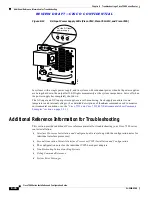
Figure 8-5
Front Panel LEDs (Cisco 7513, Cisco 7513-MX, and Cisco 7576)
Using the RSP LEDs
This section describes the indications for the LEDs on the RSPs.
RSP2 LEDs—Cisco 7500 Series
The two LEDs on the RSP2—normal and CPU halt (see
Figure 8-6
)—indicate the system and RSP2
status. The normal LED goes on to indicate that the system is operational. During normal operation, the
CPU halt LED on the RSP2 should be off and stay off unless the system detects a processor hardware
failure. A successful boot is indicated when the normal LED comes on and stays on; however, this does
not necessarily mean that the system has reached normal operation.
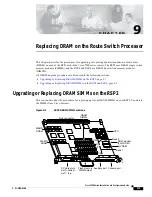
The slot 0 and slot 1 LEDs indicate which PC Card (Flash memory card) slot is in use and blink when
either slot is being accessed by the system.
Figure 8-6
RSP2 LEDs (Partial Front Panel, Horizontal View)
POWER
A
POWER
B
NORMAL
POWER
A
POWER
B
NORMAL
SERIES
H3088
NORMAL
RESET
CPU HALT
H10236
EJECT
SLOT 1
SLOT 0
MASTER
SLAVE
SLAVE/MASTER


