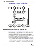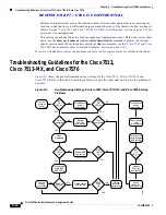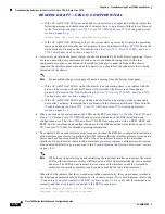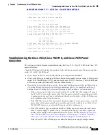
R E V I E W D R A F T — C I S C O C O N F I D E N T I A L
8-22
Cisco 7500 Series Installation and Configuration Guide
OL-5008-03 B0
Chapter 8 Troubleshooting a Cisco 7500 Series Router
Using Cisco 7500 Series System LEDs
Caution
The reset switch resets the RSP2 and the entire system. To prevent system errors and problems, use it
only at the direction of your service representative.
Note
The function of the master/slave switch, not available with the first release of the RSP2, allows you to
designate which RSP2 acts as the system master and which as the slave. This functionality is only
relevant for systems using two RSP2 processor modules in slot 6 and slot 7. RSP2s as spares are shipped
as system masters by default. If two RSP2s are installed, one must be the master and one must be the
slave, regardless of the slot in which they are installed (slot 2 and slot 3 in the Cisco 7507 and Cisco
7507-MX; slot 6 or slot 7 in the Cisco 7513 and Cisco 7513-MX).
The Cisco 7576 does not support master/slave operation. Only one RSP is used per router; therefore, the
RSP in slot 6 is automatically the system master for router A, and the RSP in slot 7 is automatically the
system master for router B.
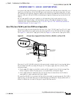
RSP4 and RSP8 LEDs—Cisco 7500 Series
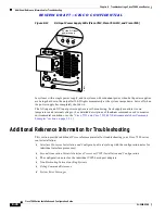
Figure 8-7
shows the LEDs on the RSP4 and RSP8 faceplate. The LEDs on the RSP4 and RSP8 indicate
the system and RSP4 or RSP8 status and which Flash memory card slot is active. The CPU halt LED,
which goes on only if the system detects a processor hardware failure, should remain off. A successful
boot is indicated when the normal LED goes on; however, this does not necessarily mean that the system
has reached normal operation. During normal operation, the CPU halt LED should be off, and the normal
LED should be on, indicating that the RSP4 or RSP8 is rec5V. The slot 0 and slot 1 LEDs
indicate which PC Card (Flash memory) card slot is in use, and each LED blinks when the card is
accessed by the system. The master and slave LEDs provide a visual indication of whether the RSP4 is
designated as a master or a slave device.
Note
The Cisco 7576 does not support master/slave operation. Only one RSP is used per router, designated
router A and router B within the chassis; therefore, the RSP in slot 6 is automatically the system master
for router A, and the RSP in slot 7 is automatically the system master for router B.
Figure 8-7
RSP4 and RSP8 LEDs (Partial Front Panel, Horizontal View)
Caution
The reset switch (see
Figure 8-7
) resets the RSP4 or RSP8 and the entire system. To prevent system
errors and problems, use it only at the direction of your Cisco-certified service representative.
NORMAL
CPU HALT
H9725
RESET
SLOT 1
SLOT 0
MASTER
SLAVE
SLAVE/MASTER


