R E V I E W D R A F T — C I S C O C O N F I D E N T I A L
8-26
Cisco 7500 Series Installation and Configuration Guide
OL-5008-03 B0
Chapter 8 Troubleshooting a Cisco 7500 Series Router
Additional Reference Information for Troubleshooting
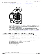
Figure 8-12
DC-Input Power Supply LEDs (Cisco 7513, Cisco 7513-MX, and Cisco 7576)
In systems with a single power supply, and in systems with redundant power when both power supplies
are being shut down, the output fail LED lights momentarily as the system ramps down, but is off when
the power supply has completely shut down.
The AC-input and DC-input power supplies are self-monitoring. Each supply monitors its own
temperature and internal voltages. (For detailed descriptions of the show commands used to monitor
environmental conditions, see the
“Cisco 7513 and Cisco 7513-MX Environmental show Command
Examples” section on page 2-31
.)
Additional Reference Information for Troubleshooting
This section provides additional Cisco reference material for troubleshooting your Cisco 7500 series
router installation:
•
Interface Processor Installation and Configuration Guide (along with the configuration notes for
individual interface processors)
•
Second-Generation Versatile Interface Processor (VIP2) Installation and Configuration
•
The configuration notes for the individual VIP2-based port adapters
•
Troubleshooting Internetworking Systems
•
Debug Command Reference
•
System Error Messages
H4285
0
I
OK
OK
FAIL
DC
FAN OUTPUT
OK
OK
FAIL
DC
FAN OUTPUT
For the DC-input
power supply

