Preparing
Network
Connections
HSSI
Connection
Equipment
You
will
need
T3 E3
or
SONET
STS-1
DSU
and
HSSI
interface
cable
to
connect
the
HIP
with
the external
network
The
HTP HSSI
interface
port
is
50-pin
SCSI-il-type
receptacle
The
HSSI
interface
cable
comprises
25
twisted
pairs
and
50-pin
plug
at
each
end
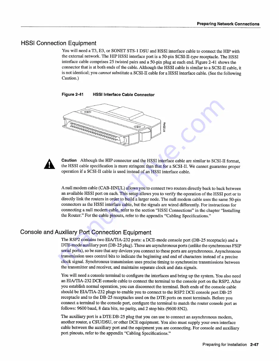
Figure
2-41
shows
the
connector
that
is
at
both
ends
of the cable
Although
the
HSSI
cable
is
similar
to
SCSI-TI
cable
it
is
not identical
you cannot
substitute
SCSI-IT
cable
for
HSSI
interface
cable
See
the following
Caution
Figure
2-41
HSSI
Interface
Cable
Connector
Caution
Although
the
HIP
connector
and
the
HSSI
interface
cable
are
similar
to
SCSI-TI
format
the
HSSI
cable
specification
is
more
stringent
than
that
for
SCSI-TI
We
cannot
guarantee
proper
operation
if
SCSI-IT
cable
is
used
instead
of an
HSSI
interface
cable
null
modem
cable
CAB-HNUL
allows
you
to
connect
two
routers
directly
back
to
back
between
an
available
HSSI
port
on each
This
setup
allows
you
to
verify the operation
of the
HSSI
port
or
to
directly
link the routers
in
order
to
build
larger
node
The
null
modem
cable
uses the
same
50-pin
connectors
as
the
HSSI
interface
cable
but the
signals
are wired
differently
For
instructions
for
connecting
null
modem
cable
refer
to
the section
HSSI
Connections
in
the chapter
Installing
the
Router
For
the cable
pinouts
refer
to
the appendix
Cabling
Specifications
Console
and
Auxiliary Port
Connection
Equipment
The
RSP2
contains
two EIA/TIA-232
ports
DCE-mode
console
port
DB-25
receptacle
and
DTE-mode
auxiliary
port
DB-25
plug
These
are asynchronous
ports
unlike
the synchronous
FSIP
serial
ports
so
be
sure
that
any
devices
you
connect
to
these
ports
are
asynchronous
Asynchronous
transmission
uses control
bits
to
indicate
the beginning
and end
of characters
instead
of
precise
clock
signal
Synchronous
transmission
uses
precise
timing
to
synchronize
transmissions
between
the transmitter
and
receiver
and
maintains
separate
clock
and
data
signals
You
will
need
console
terminal
to
configure
the
interfaces
and
bring
up
the
system You
also
need
an
EIAITIA-232
DCE
console
cable
to
connect
the terminal
to
the console
port
on
the
RSP2
After
you
establish
normal
operation
you
can
disconnect
the terminal
Both
ends
of the console
cable
should
be EIAITIA-232
plugs
to
enable
you
to
connect
to
the
RSP2
DCE
console
port
DB-25
receptacle
and
to
the
DB-25
receptacles
used
on
the
DTE
ports
on most
terminals
Before
you
connect
terminal
to
the console
port
configure
the terminal
to
match
the router
console
port
as
follows 9600
baud
data
bits
no
parity
and
stop
bits
9600
8N2
The
auxiliary
port
is
DTE
DB-25
plug
that
you
can
use
to
connect
an
asynchronous
modem
another
router
CSUIDSU
or other
DCE
equipment
You
also
must
supply
your
own
interface
cable
between
the auxiliary port
and
the
equipment
you
are
connecting For
console
and
auxiliary
port
pinouts
refer
to
the appendix
Cabling
Specifications
Preparing
for
Installation
2-47
Summary of Contents for 7513 Series
Page 1: ......
Page 11: ...Cisco 7513 Hardware Installation and Maintenance ...
Page 121: ...Site Log 2 56 Cisco 7513 Hardware Installation and Maintenance ...
Page 162: ...Troubleshooting the Processor Subsystem 4 10 Cisco 7513 Hardware Installation and Maintenance ...
Page 266: ...Interface Processor LEDs B 16 Cisco 7513 Hardware Installation and Maintenance ...
Page 270: ...C 4 Cisco 7513 Hardware Installation and Maintenance ...
Page 288: ...18 Cisco 7513 Hardware Installation and Maintenance ...


