Router
Installation
Checklist
Zone
names
network
numbers
or
node
numbers
for the
new
interfaces
if
required
Operating
speeds
for
specific
interfaces
for
example
Token
Ring
interfaces
operate
at
either
or
16
Mbps
and
serial
interfaces
operate
at
speeds
of
up
to
2Mbps
The
speed
of an interface
often
depends on
the speed
of the
remote
device
to
which
it
is
attached
For
complete
configuration
instructions
refer
to
the
Router
Products
Configuration
Guide
which
is
available
on UniverCD
or
in
Router
Installation
Checklist
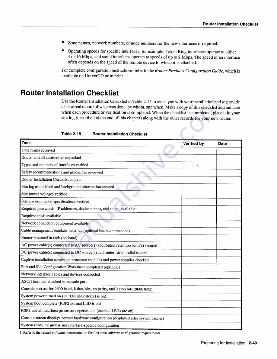
Use
the Router
Installation
Checklist
in
Table
2-15
to
assist
you
with
your
installation
and
to
provide
historical
record
of
what was done
by
whom
and
when
Make
copy
of
this
checklist
and
indicate
when
each
procedure
or
verification
is
completed
When
the checklist
is
completed
place
it
in
your
site
log
described
at
the
end
of
this
chapter
along
with
the other
records
for
your
new
router
Table
2-15
Router
Installation
Checklist
Task
Verified
by
Date
Date
router
received
Router
and
all
accessories
unpacked
Types
and
numbers
of
interfaces
verified
Safety
recommendations
and
guidelines
reviewed
Router
Installation
Checklist
copied
Site
log
established
and
background
information
entered
Site
power
voltages
verified
Site
environmental
specifications
verified
Required
passwords
IP addresses
device
names
and
so
on
available1
Required
tools
available
Network
connection
equipment
available
Cable
management
brackets
installed
optional
but
recommended
Router
mounted
in
rack
optional
AC
power
cables
connected
to
AC
sources
and
router
retention
bands
secured
DC
power
cables
connected
to
DC
sources
and router
strain
relief secured
Captive
installation
screws
on processor modules and power
supplies
checked
Port and
Slot
Configuration
Worksheet
completed
optional
Network
interface
cables
and
devices
connected
ASCII
terminal
attached
to
console
port
Console
port
set
for
9600
baud
data
bits
no
parity
and
stop
bits
9600
8N2
System
power
turned
on
DC
OK
indicators
is
on
System
boot
complete
RSP2
normal
LED
is
on
RSP2
and
all
interface
processors
operational
enabled
LEDs
are
on
Console
screen
displays
correct
hardware
configuration
displayed
after
system
banner
System
ready
for
global
and
interface-specific
configuration
Refer
to
the
related
software
documentation
for
first-time
software
configuration
requirements
Preparing
for
Installation
2-49
Summary of Contents for 7513 Series
Page 1: ......
Page 11: ...Cisco 7513 Hardware Installation and Maintenance ...
Page 121: ...Site Log 2 56 Cisco 7513 Hardware Installation and Maintenance ...
Page 162: ...Troubleshooting the Processor Subsystem 4 10 Cisco 7513 Hardware Installation and Maintenance ...
Page 266: ...Interface Processor LEDs B 16 Cisco 7513 Hardware Installation and Maintenance ...
Page 270: ...C 4 Cisco 7513 Hardware Installation and Maintenance ...
Page 288: ...18 Cisco 7513 Hardware Installation and Maintenance ...


