Connecting
Power
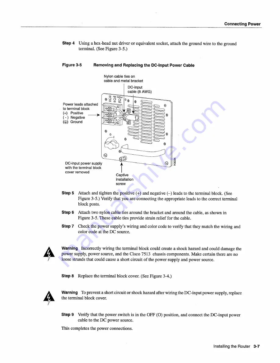
Step
Using
hex-head
nut driver or equivalent
socket
attach the
ground
wire
to
the
ground
terminal
See
Figure
3-5
Figure
3-5
Removing
and
Replacing
the
DC-Input Power
Cable
Power
leads
attached
to
terminal
block
Positive
______
Negative
Ground
DC-input
power
supply
with
the
terminal
block
cover
removed
Nylon
cable
ties
on
cable
and
metal
bracket
Step
Attach
and
tighten
the positive
and
negative
leads
to
the terminal
block
See
Figure
3-5
Verify
that
you
are connecting
the appropriate
leads
to
the correct
terminal
block
posts
Step
Attach
two
nylon
cable
ties
around
the bracket
and
around
the cable
as
shown
in
Figure
3-5 These
cable
ties
provide
strain
relief
for
the cable
Step
Check
the
power supplys
wiring
and
color
code
to
verify
that
they
match
the wiring
and
color
code
at
the
DC
source
Warning
Incorrectly
wiring
the terminal
block
could
create
shock
hazard
and
could
damage
the
power
supply power source and
the Cisco
7513
chassis
components
Make
certain
there
are
no
loose
strands
that
could
cause
short
circuit
of the
power
supply
and
power
source
Step
Replace
the terminal
block
cover
See
Figure
3-4
Warning
To
prevent
short
circuit
or
shock
hazard
after
wiring
the
DC-input power supply
replace
the terminal
block
cover
Step
Verify
that
the
power
switch
is in
the
OFF
position
and
connect
the
DC-input power
cable
to
the
DC
power
source
This
completes
the
power
connections
Captive
installation
screw
Installing
the
Router
3-7
Summary of Contents for 7513 Series
Page 1: ......
Page 11: ...Cisco 7513 Hardware Installation and Maintenance ...
Page 121: ...Site Log 2 56 Cisco 7513 Hardware Installation and Maintenance ...
Page 162: ...Troubleshooting the Processor Subsystem 4 10 Cisco 7513 Hardware Installation and Maintenance ...
Page 266: ...Interface Processor LEDs B 16 Cisco 7513 Hardware Installation and Maintenance ...
Page 270: ...C 4 Cisco 7513 Hardware Installation and Maintenance ...
Page 288: ...18 Cisco 7513 Hardware Installation and Maintenance ...


