Connecting
Interface
Cables
Channel
Attachment
Connections
Connecting
bus
and
tag or Enterprise
System Connection
ESCON
cables
between
the
CIP and
host processor
is
beyond
the scope
of
this
publication
The
specific
CIP
connection
requirements
are
discussed
in
detail
in the
Channel
Interface
Processor
CIP
Installation
and
Configuration
publication
Document
Number
78-1342-xx
This
configuration
note which
ships with
the
CIP
installed
in
your
chassis
is
available
on UniverCD
or in print
Token
Ring Connections
Each
Token
Ring
interface
connects
to
the ring through
MAU
or
multistation access
unit
MSAU
which
should
already
be
connected
to
the ring
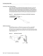
See
Figure
3-10
Connect
the
Type
or
1pe
lobe cables
to
the appropriate
TRIP
ports
and
tighten
the
thumbscrews
to
secure
the
cable
in
the port
and
provide
strain
relief
Then
connect
the
network
end
of each
lobe cable
to
the
MAU
or
MSAU
For
descriptions
of the connection
equipment
refer
to
the section
Token
Ring
Connection
Equipment
in
the chapter
Preparing
for Installation
Figure
3-10
Token
Ring
Connections
The
speed
of each
Token
Ring
port
must match
the speed
of the ring
to
which
it
is
connected
The
default
speed
for
all
TRIP
ports
is
Mbps
which
you
can
change
to
16
Mbps
on any
port with
the
configuration
command
ring-speed
where
is
the speed
or
16
in
Mbps
Before
you
enable
the
Token
Ring
interfaces
ensure
that
each
is
set
for the correct
speed
or
it
can
bring
the ring
down
The
following
sample
session changes
the ring speed
on Token
Ring
port
1/2
from
the default
Mbps
to
16Mbps
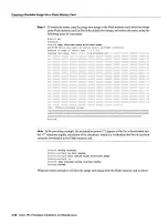
Router
configure
tenninal
Enter
configuration
commands
one
per
line
End
with
CNTL/Z
Router
config
mt
tokenring
1/2
Router
configif
ring-epeed
16
Router
configif
Router
copy
running-config
startup-config
Router
Caution
To
prevent
problems on
the ring each
TRIP
port
must be
configured
for the
same
ring
speed
as
the ring
to
which
it
is
connected
either
or 16
Mbps
If
the port
is set
for
different
speed
it
will cause
the ring
to
beacon
which
effectively
brings
the ring
down
and makes
it
inoperable
Type
lobe
cable
TRIP
3-14
Cisco
7513
Hardware
Installation
and
Maintenance
Summary of Contents for 7513 Series
Page 1: ......
Page 11: ...Cisco 7513 Hardware Installation and Maintenance ...
Page 121: ...Site Log 2 56 Cisco 7513 Hardware Installation and Maintenance ...
Page 162: ...Troubleshooting the Processor Subsystem 4 10 Cisco 7513 Hardware Installation and Maintenance ...
Page 266: ...Interface Processor LEDs B 16 Cisco 7513 Hardware Installation and Maintenance ...
Page 270: ...C 4 Cisco 7513 Hardware Installation and Maintenance ...
Page 288: ...18 Cisco 7513 Hardware Installation and Maintenance ...


