Troubleshooting
the
Power
Subsystem
Use
duplication
or
disclosure
by
the
Government
is
subject
to
restrictions
as
set
forth
in
subparagraph
of
the
Commercial
Computer
Software
Restricted
Rights
clause
at
FAR
sec
52.227-19
and
subparagraph
ii
of
the
Rights
in
Technical
Data
and
Computer
Software
clause
at
DFARS
sec
252.227-7013
cisco
Systems
Inc
170
Tasman
Drive
San
Jose
CA
95134
GS
Software
RSP-K
Version
10.3571
RELEASE
SOFTWARE
Copyright
1986-1995
by
cisco
Systems
Inc
text
omitted
Press
RETURN
to
get
started
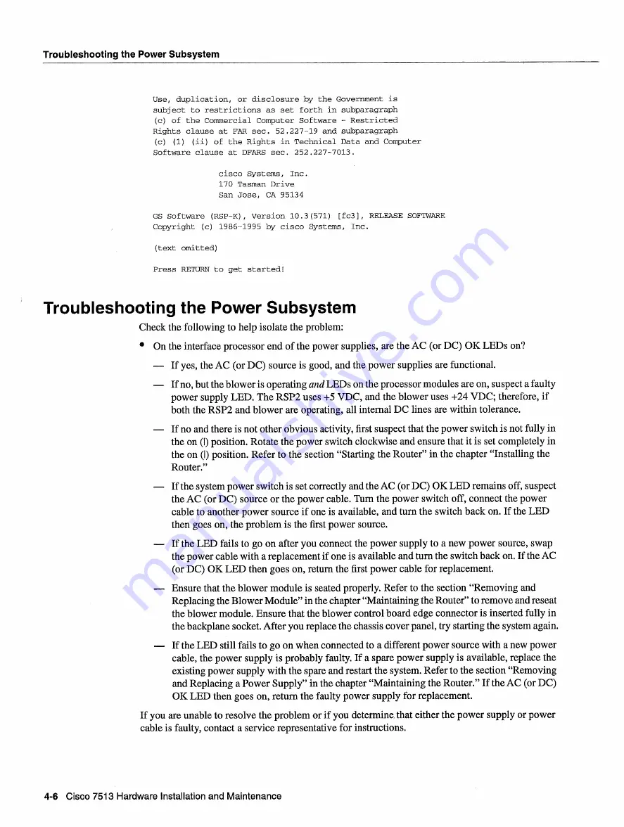
Troubleshooting
the
Power Subsystem
Check
the following
to
help
isolate
the
problem
On
the interface
processor
end
of the
power
supplies
are
the
AC
or
DC
OK
LEDs
on
If
yes
the
AC
or
DC
source
is
good
and
the
power
supplies
are
functional
If
no
but the
blower
is
operating
and
LEDs
on
the processor
modules
are
on
suspect
faulty
power
supply
LED
The
RSP2
uses
VDC
and
the
blower
uses
24 VDC
therefore
if
both
the
RSP2
and blower
are
operating
all internal
DC
lines
are
within
tolerance
If
no and
there
is
not other
obvious
activity
first
suspect
that
the
power
switch
is
not
fully
in
the
on
position
Rotate
the
power
switch
clockwise
and
ensure
that
it
is
set
completely
in
the
on
position
Refer
to
the section
Starting
the
Router
in
the chapter
Installing
the
Router
If
the system
power
switch
is set
correctly
and
the
AC
or
DC
OK
LED
remains
off
suspect
the
AC
or
DC
source
or the
power
cable
Turn
the
power
switch
off
connect
the
power
cable
to
another
power
source
if
one
is
available
and
turn
the switch
back
on
If
the
LED
then
goes
on
the
problem
is
the
first
power
source
If
the
LED
fails
to
go on
after
you
connect
the
power
supply
to
new
power
source swap
the
power
cable
with
replacement
if
one
is
available
and
turn
the switch
back
on
If
the
AC
or
DC
OK
LED
then
goes
on
return
the
first
power
cable
for
replacement
Ensure
that
the
blower module
is
seated
properly
Refer
to
the section
Removing
and
Replacing
the
Blower
Module
in
the chapter
Maintaining
the
Router
to
remove
and
reseat
the
blower
module
Ensure
that
the
blower
control
board edge
connector
is
inserted
fully
in
the backplane
socket
After
you
replace
the chassis cover
panel
try
starting
the system
again
If
the
LED
still
fails
to
go on
when
connected
to
different
power
source
with
new
power
cable
the
power
supply
is
probably
faulty
If
spare
power
supply
is
available
replace
the
existing
power
supply
with
the spare
and
restart
the
system
Refer
to
the section
Removing
and
Replacing
Power
Supply
in
the chapter
Maintaining
the
Router
If
the
AC
or
DC
OK
LED
then
goes
on
return
the
faulty
power
supply
for
replacement
If
you
are unable
to
resolve
the
problem
or
if
you
determine
that
either
the
power
supply
or
power
cable
is
faulty
contact
service
representative
for instructions
4-6
Cisco
7513
Hardware
Installation
and
Maintenance
Summary of Contents for 7513 Series
Page 1: ......
Page 11: ...Cisco 7513 Hardware Installation and Maintenance ...
Page 121: ...Site Log 2 56 Cisco 7513 Hardware Installation and Maintenance ...
Page 162: ...Troubleshooting the Processor Subsystem 4 10 Cisco 7513 Hardware Installation and Maintenance ...
Page 266: ...Interface Processor LEDs B 16 Cisco 7513 Hardware Installation and Maintenance ...
Page 270: ...C 4 Cisco 7513 Hardware Installation and Maintenance ...
Page 288: ...18 Cisco 7513 Hardware Installation and Maintenance ...


