Removing
and
Replacing
Chassis
Components
Step
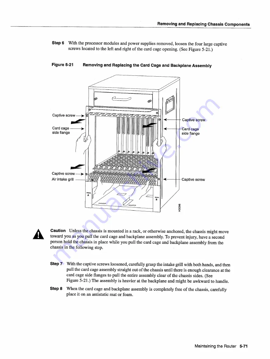
With
the processor
modules
and
power
supplies
removed
loosen
the four large captive
screws
located
to
the
left
and
right
of the card
cage
opening
See
Figure
521
Figure
5-21
Removing
and
Replacing
the
Card
Cage
and
Backplane
Assembly
Caution
Unless
the chassis
is
mounted
in
rack
or otherwise
anchored
the chassis
might
move
toward
you
as
you
pull the card
cage
and
backplane
assembly
To
prevent
injury
have
second
person
hold
the chassis in place
while
you
pull
the card
cage
and
backplane
assembly from
the
chassis in the following
step
Step
With
the captive screws
loosened
carefully grasp
the intake
grill
with
both
hands
and
then
pull
the card
cage
assembly
straight
out of the chassis
until
there
is
enough
clearance
at
the
card
cage
side flanges
to
pull the
entire
assembly
clear
of the chassis
sides
See
Figure
5-21
The
assembly
is
heavier
at
the backplane
and might be awkward
to
handle
Step
When
the card
cage
and
backplane
assembly
is
completely
free
of the chassis
carefully
place
it
on
an
antistatic
mat
or
foam
screw
Maintaining
the
Router
5-71
Summary of Contents for 7513 Series
Page 1: ......
Page 11: ...Cisco 7513 Hardware Installation and Maintenance ...
Page 121: ...Site Log 2 56 Cisco 7513 Hardware Installation and Maintenance ...
Page 162: ...Troubleshooting the Processor Subsystem 4 10 Cisco 7513 Hardware Installation and Maintenance ...
Page 266: ...Interface Processor LEDs B 16 Cisco 7513 Hardware Installation and Maintenance ...
Page 270: ...C 4 Cisco 7513 Hardware Installation and Maintenance ...
Page 288: ...18 Cisco 7513 Hardware Installation and Maintenance ...


