MIP
Interface
Cable
Pinouts
MIP
Interface
Cable Pinouts
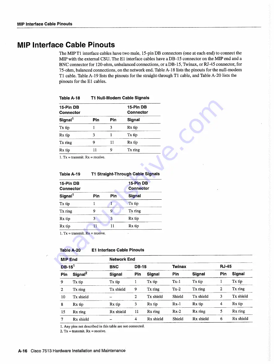
The
MIP
Ti
interface
cables
have
two male
15-pin
DB
connectors
one
at
each
end
to
connect
the
MIP
with
the external
CSU
The
El
interface
cables
have
DB-15
connector
on
the
MIP
end and
BNC
connector
for
120-ohm
unbalanced
connections
or
DB- 15 Twinax
or
RJ-45
connector
for
75-ohm
balanced
connections
on
the
network
end
Table
A-18
lists
the pinouts for the
null-modem
Ti
cable
Table
A-19
lists
the pinouts
for
the
straight-through
Ti cable and
Table
A-20
lists
the
pinouts
for the
El
cables
Table
A-la
Ti
Null-Modem
Cable
Signals
15-Pin
DB
15-Pin
DB
Connector
Connector
Signal1
Pin
Pin
Signal
Txtip
Rxtip
Rxtip
Txtip
Txring
11
Rxtip
Rxtip
11
Txring
Tx
transmit
Rx
receive
Table
A-19
Ti
Straight-Through
Cable
Signals
15-Pin
DB
15-Pin
DB
Connector
Connector
Signal1
Pin
Pin
Signal
Txtip
Txtip
Txring
Txring
Rxtip
Rxtip
Rxtip
11
11
Rxtip
Tx
transmit
Rx
receive
Table
A-20
El
Interface
Cable
Pinouts
MIP
End
Network
End
DB-15
BNC
DB-15
Twinax
RJ-45
Pin
Signal2
Signal
Pin
Signal
Pin
Signal
Pin
Signal
Tx
tip
Tx
tip
Tx
tip
Tx-i
Tx
tip
Tx
tip
Tx
ring
Tx
shield
Tx
ring
Tx-2
Tx
ring
Tx
ring
10
Tx
shield
Tx
shield
Shield
Tx
shield
Tx
shield
Rx
tip
Rx
tip
Rx
tip
Rx-i
Rx
tip
Rx
tip
15
Rx
ring
Rx
shield
11
Rx
ring
Rx-2
Rx
ring
Rx
ring
Rx
shield
Rx
shield
Shield
Rx
shield
Rx
shield
Any
pins
not described
in
this
table
are not connected
Tx
transmit
Rx
receive
A-16
Cisco
7513
Hardware
Installation
and
Maintenance
Summary of Contents for 7513 Series
Page 1: ......
Page 11: ...Cisco 7513 Hardware Installation and Maintenance ...
Page 121: ...Site Log 2 56 Cisco 7513 Hardware Installation and Maintenance ...
Page 162: ...Troubleshooting the Processor Subsystem 4 10 Cisco 7513 Hardware Installation and Maintenance ...
Page 266: ...Interface Processor LEDs B 16 Cisco 7513 Hardware Installation and Maintenance ...
Page 270: ...C 4 Cisco 7513 Hardware Installation and Maintenance ...
Page 288: ...18 Cisco 7513 Hardware Installation and Maintenance ...


