Interface
Processor
LEDs
TRIP
LEDs
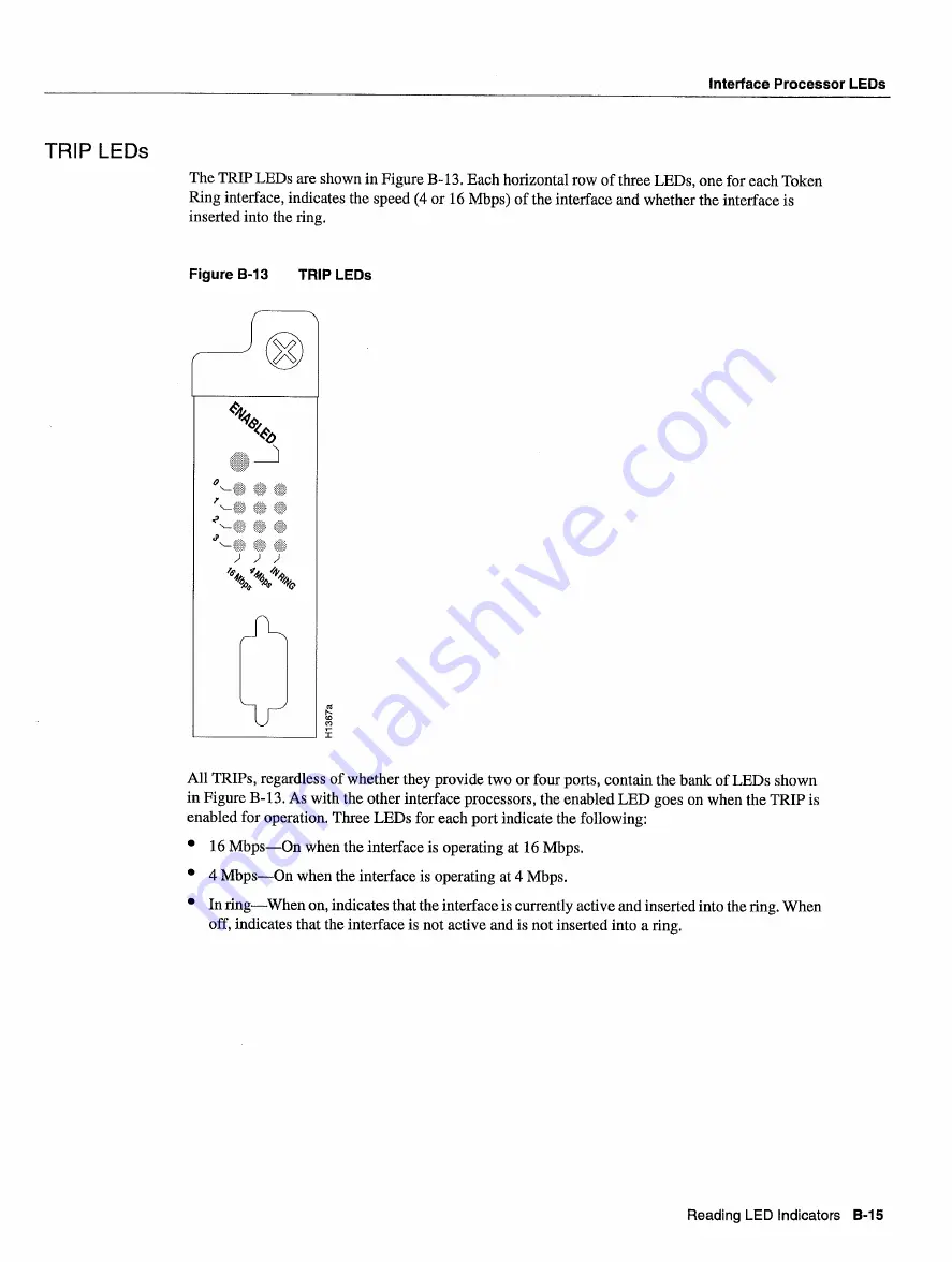
The
TRIP LEDs
are
shown
in
Figure
B.-
13
Each
horizontal
row
of three
LEDs
one
for
each
Token
Ring
interface
indicates
the
speed
or
16
Mbps
of the interface
and
whether
the interface
is
inserted
into
the ring
Figure
B-13
TRIP
LEDs
CD
All
TRIPs
regardless
of
whether
they provide
two
or four
ports
contain
the
bank
of
LEDs
shown
in Figure
B-13
As
with
the other
interface
processors
the enabled
LED
goes
on
when
the
TRIP
is
enabled
for operation
Three
LEDs
for
each
port
indicate
the following
16
MbpsOn
when
the interface
is
operating
at
16
Mbps
MbpsOn
when
the interface
is
operating
at
Mbps
In
ringWhen
on
indicates
that
the interface
is
currently active
and
inserted
into
the ring
When
off
indicates
that
the interface
is
not
active
and
is
not inserted
into
ring
Reading
LED
Indicators
B-15
Summary of Contents for 7513 Series
Page 1: ......
Page 11: ...Cisco 7513 Hardware Installation and Maintenance ...
Page 121: ...Site Log 2 56 Cisco 7513 Hardware Installation and Maintenance ...
Page 162: ...Troubleshooting the Processor Subsystem 4 10 Cisco 7513 Hardware Installation and Maintenance ...
Page 266: ...Interface Processor LEDs B 16 Cisco 7513 Hardware Installation and Maintenance ...
Page 270: ...C 4 Cisco 7513 Hardware Installation and Maintenance ...
Page 288: ...18 Cisco 7513 Hardware Installation and Maintenance ...


