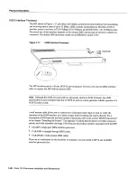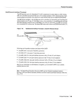
Physical
Description
There
are
no
restrictions
on
slot
locations
or
sequence
you can
install
FSIPs
in
any
available
interface
processor
slots
For
descriptions
of
serial
connection
equipment
refer
to
the section
Serial
Connection
Equipment
in the chapter
Preparing
for
Installation
For examples
of
network
connections
refer
to
the section
Serial
Connections
in
the chapter
Installing
the
Router
All interface
types except
EIA-530
and El-G.703/G.704
are individually
configurable
for
operation
with
either
external
timing
DTE
mode
or
internal
timing
DCE
mode
EIA-530
operates
with
external
timing
only
In addition
all interfaces
support
nonreturn
to
zero
NRZ
and
nonreturn
to
zero inverted
NRZI
format
and
both
16-bit
and
32-bit cyclic
redundancy
checks
CRC5
The
default
configuration
is
for
NRZ
format
and
16-bit
CRC
You
can
change
these
default
settings
with
software
commands
See
the section
Configuring
the
FSIP
in
the chapter
Maintaining
the
Router
In order
to
provide
high
density
of ports
the
FSIP
uses
special port
adapters
and
adapter
cables
port
adapter
is
daughter
card
that
provides
the physical
interface
for
two FSIP
ports
Both
ports
use
the
same
high-density
60-pin
universal
receptacle
that
supports
all
interface
types
The
adapter
cable
connected
to
the port determines
the interface
type
and
mode
The
interface
ports
are not
set
to
default
mode
or for
default
clock
source
so there
are
no
software
commands
required
to
enable
internal
or external
timing
DCE
or
DTE
Each
port
automatically
supports
the
mode
of the port adapter
cable
when
one
is
connected
However
there
is
no
default
clockrate
set
You must
set
the clock
rate
on
all
DCE
ports with
the clockrate
command
before
the
port
can
operate
with
an
external
timing
signal
To
use the port
as
DCE
interface
you must
set
the clock
rate
and
connect
DCE
adapter
cable
To
use
the port
as
DTE
interface
you need
only
connect
DTE
adapter
cable
to
the port
If
you
connect
DTE
cable
to
port
on which
clock
rate
is
set
the system
will
ignore
the clock
rate
until
DCE
cable
is
attached
For example
you
can
change
an interface
from
an
EIAITIA-232
to
V.35
by
replacing
the adapter
cable
or
change
the
mode
of an
EIA/TIA-232
DTE
port
by
replacing
the
EIAITIA-232
DTE
cable
with
an
EIA/TIA-232
DCE
cable
provided
that
you have
already
specified
clock
rate
for
the port
Note
Although no
software
configuration
is
necessary
to
enable
internal
clocking
for
DCE
mode
you
cannot
bring
up
DCE
interface
until
you
set
the clock
rate
For
brief description
of the
clockrate
command
refer
to
the section
Configuring
the
FSIP
in the chapter
Maintaining
the
Router
For
complete
command
descriptions
and
instructions
refer
to
the related
software
documentation
Universal
Serial
Port
Adapters
The
FSIP
uses
special universal
serial
port adapters
and
adapter
cables
to
allow
up
to
eight
interface
ports
on
an
FSIP
regardless
of the
size
or
form
factor
of the connectors
typically
used
with
each
electrical
interface
type
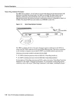
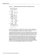
Figure
1-15
shows
universal
port
adapter
with
the 60-pin
connectors
that
support
all
interface
types
The
adapter
cable
connected
to
the port determines
the interface
type
and
mode
The
universal
port
adapters
are
field-replaceable
daughter
cards
mounted
to
the
FSIP
and
each
provides
two
high-density
connectors
for
two FSIP
ports
See
Figure
1-15
The
60-pin
D-shell
receptacle
supports
EIA/TIA-232
V.35
EIA/TIA-449
X.21
and
EIA-530
Product
Overview
1-25
Summary of Contents for 7513 Series
Page 1: ......
Page 11: ...Cisco 7513 Hardware Installation and Maintenance ...
Page 121: ...Site Log 2 56 Cisco 7513 Hardware Installation and Maintenance ...
Page 162: ...Troubleshooting the Processor Subsystem 4 10 Cisco 7513 Hardware Installation and Maintenance ...
Page 266: ...Interface Processor LEDs B 16 Cisco 7513 Hardware Installation and Maintenance ...
Page 270: ...C 4 Cisco 7513 Hardware Installation and Maintenance ...
Page 288: ...18 Cisco 7513 Hardware Installation and Maintenance ...

