background image

B-1

Cisco Aironet 1540 Series Outdoor Access Point Hardware Installation Guide


A P P E N D I X


B

Declarations of Conformity and 
Regulatory Information

This appendix provides declarations of conformity and regulatory information for the Cisco Aironet 
1542 Outdoor Access Point.

This appendix contains the following sections:

Manufacturers Federal Communication Commission Declaration of Conformity Statement, 
page B-2

Industry Canada, page B-3

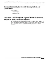
European Community, Switzerland, Norway, Iceland, and Liechtenstein, page B-6

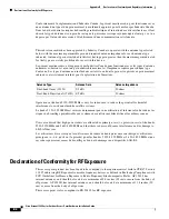
Declaration of Conformity for RF Exposure, page B-9

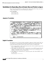
Guidelines for Operating Cisco Aironet Access Points in Japan, page B-10

VCCI Statement for Japan, page B-11

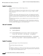
Administrative Rules for Cisco Aironet Access Points in Taiwan, page B-11

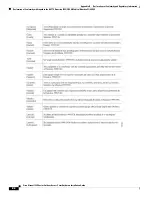
EU Declaration of Conformity, page B-13

Summary of Contents for AIR-AP1542D-*-K9

Page 1: ...Cisco has more than 200 offices worldwide Addresses phone numbers and fax numbers are listed on the Cisco website at www cisco com go offices Cisco Aironet 1540 Series Outdoor Access Points Hardware Installation Guide Text Part Number ...

Page 2: ... are encouraged to try to correct the interference by using one or more of the following measures Reorient or relocate the receiving antenna Increase the separation between the equipment and receiver Connect the equipment into an outlet on a circuit different from that to which the receiver is connected Consult the dealer or an experienced radio TV technician for help Modifications to this product...

Page 3: ...1 3 AP1542I Internal Omni Antenna 1 5 AP1542D Internal Directional Antenna 1 5 Power Sources 1 6 Ethernet PoE Ports 1 6 Network Deployment Examples 1 7 Wireless Backhaul 1 7 Point to Point Bridging 1 7 Point to Multipoint Bridging 1 8 Point to Multipoint Mesh Network 1 9 Layer 3 Network Operation 1 10 C H A P T E R 2 Installing the Access Point 2 1 Unpacking the Access Point 2 2 Package Contents 2...

Page 4: ...r List 3 3 Using DHCP Option 43 3 3 Monitoring the Access Point Status LED 3 3 Resetting the Access Point 3 6 Verifying Controller Association 3 6 Changing the Bridge Group Name 3 6 A P P E N D I X A Safety Guidelines and Warnings A 1 FCC Safety Compliance Statement A 2 Safety Precautions A 2 Performing Site Surveys A 3 Translated Safety Warnings A 4 A P P E N D I X B Declarations of Conformity an...

Page 5: ... 10 Japanese Translation B 10 English Translation B 10 VCCI Statement for Japan B 11 Administrative Rules for Cisco Aironet Access Points in Taiwan B 11 Chinese Translation B 11 English Translation B 12 Chinese Translation B 12 English Translation B 12 Statement 371 Power Cable and AC Adapter B 13 English Translation B 13 EU Declaration of Conformity B 13 Operation of Cisco Aironet Access Points i...

Page 6: ...Contents vi Cisco Aironet 1540 Series Outdoor Access Point Hardware Installation Guide ...

Page 7: ...r should be familiar with network structures terms and concepts Warning Only trained and qualified personnel should be allowed to install replace or service this equipment Statement 1030 Warning This equipment must be installed in restricted access locations in Norway Finland and Sweden Only trained and qualified personnel are allowed to install replace or service this equipment as instructed in t...

Page 8: ...onformity and Regulatory Information Describes the regulatory conventions to which the access point conforms and provides guidelines for operating access points in Japan Appendix E Access Point Pinouts Describes the connector pinouts for the access point Chapter Title Description Convention Description boldface font Commands command options and keywords are in boldface italic font Arguments for wh...

Page 9: ...in käsittelet laitteistoa huomioi sähköpiirien käsittelemiseen liittyvät riskit ja tutustu onnettomuuksien yleisiin ehkäisytapoihin Turvallisuusvaroitusten käännökset löytyvät laitteen mukana toimitettujen käännettyjen turvallisuusvaroitusten joukosta varoitusten lopussa näkyvien lausuntonumeroiden avulla SÄILYTÄ NÄMÄ OHJEET Attention IMPORTANTES INFORMATIONS DE SÉCURITÉ Ce symbole d avertissement...

Page 10: ...ção que poderá ser causadora de lesões corporais Antes de iniciar a utilização de qualquer equipamento tenha conhecimento dos perigos envolvidos no manuseio de circuitos elétricos e familiarize se com as práticas habituais de prevenção de acidentes Utilize o número da instrução fornecido ao final de cada aviso para localizar sua tradução nos avisos de segurança traduzidos que acompanham este dispo...

Page 11: ...xi Cisco Aironet 1540 Series Outdoor Access Point Hardware Installation Guide Figyelem ...

Page 12: ...ração fornecido ao final de cada aviso para localizar sua tradução nos avisos de segurança traduzidos que acompanham o dispositivo GUARDE ESTAS INSTRUÇÕES Advarsel VIGTIGE SIKKERHEDSANVISNINGER Dette advarselssymbol betyder fare Du befinder dig i en situation med risiko for legemesbeskadigelse Før du begynder arbejde på udstyr skal du være opmærksom på de involverede risici der er ved elektriske k...

Page 13: ...xiii Cisco Aironet 1540 Series Outdoor Access Point Hardware Installation Guide ...

Page 14: ...to refer to the following guides Cisco Wireless LAN Controller Configuration Guide URL to be added at CCO Release Notes for Cisco Wireless LAN Controllers and Lightweight Access Points URL to be added at CCO Cisco Mobility Express Configuration and User Guide URL to be added at CCO DHCP OPTION 43 for Lightweight Cisco Aironet Access Points Configuration Example http www cisco com c en us support d...

Page 15: ...ation and support providing documentation feedback security guidelines and recommended aliases and general Cisco documents see the monthly What s New in Cisco Product Documentation which also lists all new and revised Cisco technical documentation at http www cisco com c en us td docs general whatsnew whatsnew html To view all new wireless documentation click on Wireless ...

Page 16: ...xvi Cisco Aironet 1540 Series Outdoor Access Point Hardware Installation Guide ...

Page 17: ...e 2 4 GHz and 5 GHz radios can be used for client access backhaul traffic or both Depending on the model the access point can support data rates of up to 1 3 Gbps The access point is a standalone unit which can be wall pole or ceiling mounted depending on the model The access point can also operate as a relay node for other access points that are not directly connected to a wired network The acces...

Page 18: ...scriptions Model or part number Configuration AIR AP1542I x K9 The AP1542I has integrated omni antennas and contains a 2 4 GHz and a 5 GHz radio with an option to configure in centralized Flexconnect Mobility Express or mesh mode It can also operate as a relay node for other access points that are not directly connected to a wired network This model can be mounted vertically on a wall or pole to p...

Page 19: ...his section Ports and Connectors page 1 3 AP1542I Internal Omni Antenna page 1 5 AP1542D Internal Directional Antenna page 1 5 Power Sources page 1 6 Ports and Connectors Figure 1 1 Front and Rear Three Quarters View of the AP 1 Back side of the AP with four screw holes for fastening the pole and wall mount bracket 3 Screw holes for fastening the optional solar cover 2 Grounding pad 4 Reset button...

Page 20: ...de of the AP 1 Console port The console port is shipped with a covering cap on it Inspect the cap at the time of installation Every time the cap is removed or replaced properly tighten it If you do not tighten properly it will not meet IP67 criteria and may lead to water leaking into the unit 3 PoE In port 2 Reset button with the status LED in its center 354956 1 2 3 354957 Grounding pad on the le...

Page 21: ...band 2 4 GHz antennas with 5 dBi gain for WiFi operation 2 single band 5 GHz antennas with 5 dBi gain for WiFi operation 1 single band 2 4 GHz antenna with 3 dBi gain for BLE operation AP1542D Internal Directional Antenna The AP1542D access point 802 11b g n radio is used primarily for local access and its 802 11a n ac radio for wireless backhaul in the Mesh The 2 4 GHz b g n radio operates in 2 4...

Page 22: ... 802 3at Power Injector AIR PWRINJ6 AIR PWRINJ 30RGD1 AIR PWRINJ 60RGD1 Caution When the access point is installed outdoors or in a wet or damp location the AC branch circuit that is powering the access point should be provided with ground fault protection GFCI as required by Article 210 of the National Electrical Code NEC Ethernet PoE Ports The access point has a PoE In port The port uses an RJ45...

Page 23: ...z is called universal client access When the access point does not have a wired Ethernet connection to the controller through a switch the radio role is called a MAP The MAPs have a wireless connection through the backhaul interface to other MAPs and finally to a RAP which has an Ethernet connection through a switch to the controller MAPs may also have a wired Ethernet connection to a local LAN an...

Page 24: ...an be used as a RAP to connect multiple remote MAPs with their associated wired networks By default this capability is turned off for all access points To support Ethernet bridging you must enable bridging on the controller for each access point Wireless client access can be provided over the bridging link however if bridging between tall buildings the 2 4 GHz wireless coverage area may be limited...

Page 25: ...between the access points are referred to as the backhaul links Intelligent wireless routing is provided by the Adaptive Wireless Path protocol AWPP This enables each MAP to identify its neighbors and intelligently choose the optimal path to the RAP with the wired network connection by calculating the cost of each path in terms of signal strength and the number of hops required to get to a control...

Page 26: ...work operation Access points and controllers in Layer 3 configurations use IP addresses and UDP packets which can be routed through large networks Layer 3 operation is scalable and recommended by Cisco Figure 1 8 illustrates a typical Layer 3 wireless network configuration containing access points and a controller Figure 1 8 Typical Layer 3 Access Point Network Configuration Example 148458 ...

Page 27: ...r describes how to install the 1540 series access point and accessories It contains the following sections Unpacking the Access Point page 2 2 Mounting the Access Point page 2 5 Installing AP Cover AIR ACC1540 CVR page 2 11 Grounding the Access Point page 2 12 Powering the Access Point page 2 13 Configuring the Access Point page 2 17 ...

Page 28: ...stallation page 2 2 Package Contents Each access point package contains the following items One 1540 series access point Ground lug and screws with lock washers Plastic cable gland and rubber seal Weatherization tape and anti corrosion sealant Cisco product documentation and pointer card Wall Pole mount bracket AIR ACC1530 PMK1 Optional Tools and Hardware From Cisco Depending on what you ordered t...

Page 29: ...ls to and from the access point We recommend installing the access points no higher than 40 feet to allow support for wireless clients on the ground Best throughput is achieved when all the access points are mounted at the same height The console port is shipped with a cap on it Inspect the cap at the time of installation Every time the cap is removed or replaced properly tighten it If you do not ...

Page 30: ...ht pole Carefully review Figure 2 1 to become familiar with the system components connectors indicators cables system interconnection and grounding Figure 2 1 Components in a Typical Access Point Installation 1 Building roof overhang 6 Ground 2 Shielded outdoor rated Ethernet CAT5e or better cable1 1 Independently sourced by the user 7 Power cord 3 Water drip loop 8 Power injector 4 6 AWG copper g...

Page 31: ... wireless access points bridging techniques and grounding methods The 1540 series access point can be wall or pole mounted The available mounting options are provided in the table below AP Mounting Kit Purpose AIR ACC1530 PMK1 Fixed mounting kit for vertical mounting on wall and pole See Wall Mounting the Access Point with AIR ACC1530 PMK1 page 2 6 Pole Mounting the Access Point with AIR ACC1530 P...

Page 32: ...the mounting wall The mounting bracket screw hole locations are shown in Figure 2 2 The dimensions of the mounting bracket is shown in Figure 2 3 Step 2 Use four screws and if required wall anchors to attach the mounting plate to the mounting surface These screws and anchors are to be sourced independently Note You can use an exterior grade plywood backboard to mount the access point to stucco cem...

Page 33: ...proximately 0 13 inch 3 3 mm Step 4 Position the access point against mounting bracket such that the four support bolts on the back of the AP slot into the keyhole slots on the mounting bracket Step 5 Slide the access point down to seat it securely in the keyhole slots on the mounting bracket Note The access point should be mounted with the status LED on the base facing downwards Step 6 Using a 10...

Page 34: ...2 Mounting Bracket for Wall and Pole Mounting Figure 2 3 Mounting Bracket Dimensions in inches and millimeters 1 One of four keyhole slots for mounting the AP 3 Bracket mount holes for fastening bracket to the wall You can use bolts of up to 1 4 inch or 6 mm in diameter 2 One of four slots for steel band clamps used for pole mounting only 354865 1 3 2 ...

Page 35: ...p and bottom sets of mounting slots on the mounting bracket see Figure 2 4 Step 3 Wrap the band straps around the pole lock them and then lightly tighten the clamps using a wrench Only tighten them enough to keep the bracket from sliding down the pole Step 4 Screw an M6 bolt into each of the four bolt holes on the back side of the access point Do not screw the bolt in all the way Leave a gap of ab...

Page 36: ...t slide on the pole Ensure that the clamps are tight enough to not let the AP move Step 8 Proceed with connecting the data cables grounding the access point powering and configuring the access point Figure 2 4 AP Mounted on a Pole 1 One of four M6 keyhole slots for mounting the AP on the bracket 3 Pole wood metal or fiberglass 2 inches to 8 inches 50 mm to 203 mm diameter 2 Top and bottom steel ba...

Page 37: ...ections are made Step 1 Position and slide the cover over the AP as shown in Figure 2 5 Step 2 Align the two holes on each side of the cover with the screw holes on corresponding side of the AP Step 3 Insert and fasten 8 32 screws through the screw holes in the cover into the AP Tighten the screws to 10 lb in Figure 2 5 Installing the Cover on the AP 1 Solar Shield 3 Two of four 8 32 screws circul...

Page 38: ...copper ground wire to the supplied grounding lug Note The grounding lug and hardware used must comply with local and national electrical codes Step 3 Open the anti corrosion sealant supplied and apply a liberal amount over the metal surface called the Ground Pad where the ground strap screw holes are located see Figure 1 3 Step 4 Connect the grounding lug to the access point grounding screw holes ...

Page 39: ...by a power injector follow these steps to complete the installation Step 1 Before applying PoE to the access point ensure that the access point is grounded see the Grounding the Access Point section on page 2 12 Step 2 See the Typical Access Point Installation Components section on page 2 4 to identify the components needed for the installation Step 3 Connect a CAT5e or better Ethernet cable from ...

Page 40: ...Installing the Access Point Powering the Access Point Step 6 Connect the Ethernet cable to the access point PoE In port See Connecting an Ethernet Cable to the Access Point section on page 2 15 For details on installing Ethernet see Connecting an Ethernet Cable to the Access Point page 2 15 ...

Page 41: ...ower to the power injector and ensure all power sources to the access point are turned off Warning This unit might have more than one power supply connection All connections must be removed to de energize the unit Statement 1028 Step 2 Ensure a 6 AWG ground wire is connected to the access point see the Grounding the Access Point section on page 2 12 Step 3 Remove the covering cap from the PoE port...

Page 42: ...023 Step 7 Carefully connect the RJ45 cable connector to the PoE port on the access point Step 8 Slide the cable gland with the rubber seal towards the access point and screw the threaded end of the body into the access point and hand tighten Step 9 Use an adjustable wrench or a 28 mm wrench to tighten the threaded end of the body into the enclosure Tighten to 15 lb in Step 10 Use an adjustable wr...

Page 43: ...nt in the controller correctly the controller sends back a discovery response to the access point When that happens the access point sends out a join request to the controller and the controller responds with a join confirmation response Then the access point establishes a Control And Provisioning of Wireless Access Points CAPWAP connection to the controller and gets the shared secret configured o...

Page 44: ...2 18 Cisco Aironet 1540 Series Outdoor Access Point Hardware Installation Guide Chapter 2 Installing the Access Point Configuring the Access Point ...

Page 45: ...troubleshooting information refer to the Cisco Technical Support and Documentation website at the following URL http www cisco com cisco web support index html Sections in this chapter include Guidelines for Using the Access Point page 3 2 Using DHCP Option 43 page 3 3 Monitoring the Access Point Status LED page 3 3 Resetting the Access Point page 3 6 Verifying Controller Association page 3 6 Chan...

Page 46: ...ontrollers are configured and reachable by the access points Your controllers are configured with the access point MAC addresses and the MAC filter list is enabled Your switch must forward DHCP requests After the access points are associated to the controller you should change the bridge group name BGN from the default value With the default BGN the mesh access points MAPs can potentially try to c...

Page 47: ... MAC address and barcode is located on the bottom of the unit When two MAC addresses are shown use the top MAC address To view the MAC addresses added to the controller MAC filter list you can use the controller CLI or the controller GUI Controller CLI Use the show macfilter summary controller CLI command to view the MAC addresses added to the controller filter list Controller GUI Log into your co...

Page 48: ...tion in progress Initializing FLASH file system FLASH memory test OK Initializing Ethernet Ethernet OK Starting AP OS Initialization successful Boot loader warnings Blinking Amber Configuration recovery is in progress the Reset button has been pushed for 2 3 seconds Red There is an Ethernet failure or an image recovery the Reset button has been pushed for 20 30 seconds Blinking Green An image reco...

Page 49: ...icates a normal operating condition The unit is joined to a controller but no wireless client is associated with it Solid Green Normal operating condition with at least one wireless client associated with the unit Operating Status Blinking Amber A software upgrade is in progress Cycling through Green Red and Amber Discovery join process is in progress Rapidly cycling through Red Green Amber and Of...

Page 50: ...sumed faulty and no changes are made Verifying Controller Association To verify that your access point is associated to the controller follow these steps Step 1 Log into your controller web interface using a web browser You can also use the controller CLI show ap summary command from the controller console port Step 2 Click Wireless and verify that your access point MAC address is listed under Eth...

Page 51: ...d this point farther away are dropped as they have a different BGN To configure the BGN for the access points using the controller GUI follow these steps Step 1 Log into your controller using a web browser Step 2 Click Wireless When access points associates to the controller the access point name appears in the AP Name list Step 3 Click on an access point name Step 4 Find the Mesh Information sect...

Page 52: ...3 8 Cisco Aironet 1540 Series Outdoor Access Point Hardware Installation Guide Chapter 3 Troubleshooting Changing the Bridge Group Name ...

Page 53: ...especially qualified for such use Statement 364 Warning The cables specified in this installation guide that are used with the specified cable glands provide protection against ingress of moisture for a Type 4 IP67 classified enclosure If substitute cable are used the installer must ensure that the size OD of the cable meets the acceptable range allowed by the cable gland Warning This equipment mu...

Page 54: ...e service disconnect Warning Installation of the equipment must comply with local and national electrical codes Statement 1074 Caution All installation methods for mounting an access point on any wall surface is subject to the acceptance of local jurisdiction FCC Safety Compliance Statement The FCC with its action in ET Docket 96 8 has adopted a safety standard for human exposure to RF electromagn...

Page 55: ...icensed spectrum there may be sources of interference from other 802 11a wireless devices especially in multi tenant buildings that could degrade your 802 11 signals A site survey can determine if such interference exists at the time of deployment A proper site survey involves temporarily setting up mesh links and taking measurements to determine whether your antenna calculations are accurate Dete...

Page 56: ...utdoor Access Point Hardware Installation Guide Appendix A Safety Guidelines and Warnings Translated Safety Warnings Do you have the proper tools and equipment to complete your survey Translated Safety Warnings URL to be added at FCS ...

Page 57: ...contains the following sections Manufacturers Federal Communication Commission Declaration of Conformity Statement page B 2 Industry Canada page B 3 European Community Switzerland Norway Iceland and Liechtenstein page B 6 Declaration of Conformity for RF Exposure page B 9 Guidelines for Operating Cisco Aironet Access Points in Japan page B 10 VCCI Statement for Japan page B 11 Administrative Rules...

Page 58: ...equipment generates uses and radiates radio frequency energy and if not installed and used in accordance with the instructions may cause harmful interference However there is no guarantee that interference will not occur If this equipment does cause interference to radio or television reception which can be determined by turning the equipment off and on the user is encouraged to correct the interf...

Page 59: ...ttps www fcc gov labhelp use subject line U NII Filing Industry Canada Models IC Certification Number Canadian Compliance Statement This device complies with Industry Canada licence exempt RSS standard s Operation is subject to the following two conditions 1 this device may not cause interference and 2 this device must accept any interference including interference that may cause undesired operati...

Page 60: ...metteur Operation in the band 5150 5250 MHz is only for indoor use to reduce the potential for harmful interference to co channel mobile satellite systems La bande 5 150 5 250 MHz est réservés uniquement pour une utilisation à l intérieur afin de réduire les risques de brouillage préjudiciable aux systèmes de satellites mobiles utilisant les mêmes canaux Users are advised that high power radars ar...

Page 61: ...chtenstein Access Point Models AIR AP1542I E K9 AIR AP1542D E K9 Declaration of Conformity with regard to the R TTE Directive 1999 5 EC Medical Directive 93 42 EEC This declaration is only valid for configurations combinations of software firmware and hardware provided and supported by Cisco Systems The use of software or firmware not provided and supported by Cisco Systems may result in the equip...

Page 62: ...40 Series Outdoor Access Point Hardware Installation Guide Appendix B Declarations of Conformity and Regulatory Information Declaration of Conformity with regard to the R TTE Directive 1999 5 EC Medical Directive 93 42 EEC ...

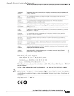
Page 63: ...y EN60950 1 2005 EN 50385 2002 Radio EN 300 328 v 1 7 1 EN 301 893 v 1 5 1 The conformity assessment procedure referred to in Article 10 4 and Annex III of Directive 1999 5 EC has been followed This device also conforms to the EMC requirements of the Medical Devices Directive 93 42 EEC Note This equipment is intended to be used in all EU and EFTA countries Outdoor use may be restricted to certain ...

Page 64: ...hes 25 cm from general bystanders The minimum separation distance from AP 1542D having internal antennas is 11 8 inches 30 cm from general bystanders Ce système a été évalué pour l exposition aux RF pour les humains en référence à la norme ANSI C 95 1 American National Standards Institute limites L évaluation a été basée sur RSS 102 Rev 2 La distance minimale de séparation de l antenne de toute pe...

Page 65: ...posure for Humans as referenced in the Australian Radiation Protection standard and has been evaluated to the ICNIRP International Commission on Non Ionizing Radiation Protection limits To maintain compliance the minimum separation distance for AP 1542I having internal antennas is 9 8 inches 25 cm from general bystanders The minimum separation distance from AP 1542D having internal antennas is 11 ...

Page 66: ...th as industrial scientific and medical devices such as microwave ovens and mobile object identification RF ID systems licensed premises radio stations and unlicensed specified low power radio stations used in factory production lines 1 Before using this equipment make sure that no premises radio stations or specified low power radio stations of RF ID are used in the vicinity 2 If this equipment c...

Page 67: ...nts in Taiwan This section provides administrative rules for operating Cisco Aironet Access Points in Taiwan The rules are provided in both Chinese and English Chinese Translation Warning This is a Class A product based on the standard of the Voluntary Control Council for Interference by Information Technology Equipment VCCI If this equipment is used in a domestic environment radio disturbance may...

Page 68: ...used the user must stop operating the device immediately and can t re operate it until the harmful interference is clear The authorized radio station means a radio communication service operating in accordance with the Communication Act The operation of the low power radio frequency devices is subject to the interference caused by the operation of an authorized radio station by another intentional...

Page 69: ...apters Using any other cables adapters could cause a malfunction or a fire Electrical Appliance and Material Safety Law prohibits the use of UL certified cables that have the UL shown on the code for any other electrical devices than products designated by CISCO The use of cables that are certified by Electrical Appliance and Material Safety Law that have PSE shown on the code is not limited to CI...

Page 70: ...gure B 1 Brazil Regulatory Information Portuguese Translation Este equipamento opera em caráter secundário isto é não tem direito a proteção contra interferência prejudicial mesmo de estações do mesmo tipo e não pode causar interferência a sistemas operando em caráter primário English Translation This equipment operates on a secondary basis and consequently must accept harmful interference includi...

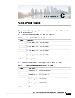
Page 71: ...power injector input connector To Switch Table C 1 Access Point LAN Connector Pinouts Pin Number Signal Name 1 Ethernet signal pair 10 100 1000BASE T 2 3 Ethernet signal pair 10 100 1000BASE T 6 4 Ethernet signal pair 10 100 1000BASE T 5 7 Ethernet signal pair 10 100 1000BASE T 8 Shield Chassis ground Table C 2 Power Injector Input Connector To Switch Pinouts Pin Number Signal Name 1 Ethernet sign...

Page 72: ...C 2 Cisco Aironet 1540 Series Outdoor Access Point Hardware Installation Guide Appendix C Access Point Pinouts ...

Reviews: