2-13
Cisco Aironet 1520 Series Outdoor Mesh Access Point Hardware Installation Guide
OL-12632-02
Chapter 2 Mounting Instructions
Installation Guidelines
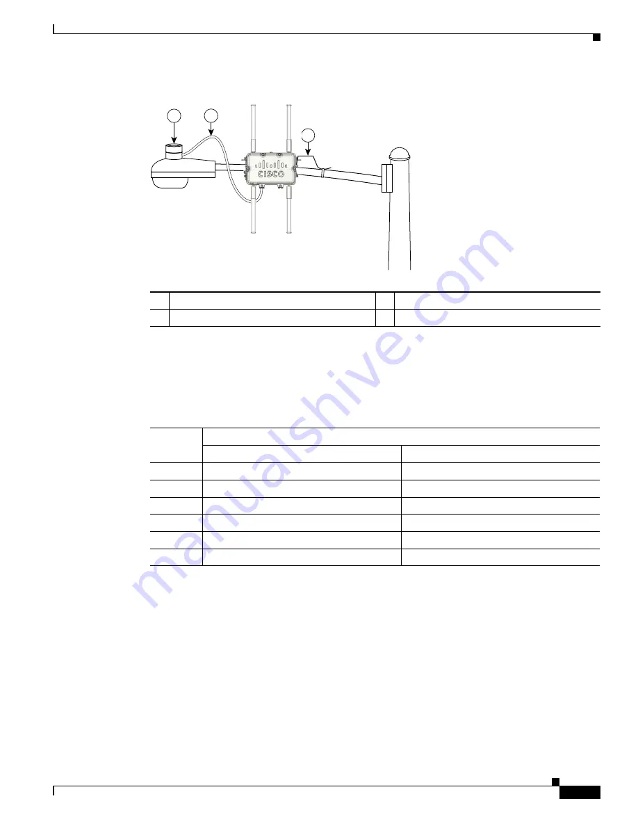
Figure 2-4
Streetlight Power Tap Adapter Installation
Antenna Connector Locations
The access point is manufactured in three configurations, cable, pole mount, and mesh. These
configurations support specific locations for the access point antennas as shown in
1
Outdoor light control
3
6-AWG copper grounding wire
2
Streetlight power tap adapter
231524
1
2
3
Table 2-1
Antenna Locations for Each Access Point Configuration
1
1.
Antenna locations specified for a two radio access point.
Antenna
Port
Access Point Configurations
Cable
Pole Mount and Mesh
1
2.4-GHz antenna connector (RX)
5-GHz antenna connector (TX/RX)
2
5-GHz antenna connector (TX/RX)
–
2
2.
Reserved for future use. A plug is installed.
3
2.4-GHz antenna connector (TX/RX)
2.4-GHz antenna connector (RX)
4
–
2
2.4-GHz antenna connector (RX)
5
–
2
–
2
6
–
1
2.4-GHz antenna connector (TX/RX)


