background image

6-6

Cisco CGR 1000 and 2000 Series Connected Grid Antennas Guide

Chapter 6      Cisco Multiband Panel Outdoor 4G MIMO Antenna (ANT-4G-PNL-OUT-N)

  Technical Specifications

880 MHz Antenna Radiation Pattern

880MHz Antenna Radiation Pattern—Horizontal Plane, page 6-6

880MHz Antenna Radiation Pattern—Vertical Plane, page 6-7

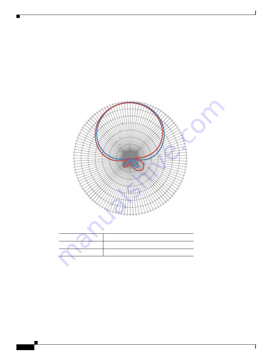
880MHz Antenna Radiation Pattern—Horizontal Plane

Figure 6-4

880 MHz Antenna Radiation Pattern—Horizontal Plane

Line Color

Description

Blue (

)

Port  1

Red (

)

Port  2

30

25

20

15

10

5

0

5

10

0

30

60

90

120

150

180

210

240

270

300

330

349222

Summary of Contents for ANT-4G-PNL-OUT-N

Page 1: ...cover cellular 4G bands The supported bands are LTE700 Cellular PCS AWS MDS global GSM900 GSM1800 UMTS LTE2600 WiMAX 2300 2500 The antenna supports the following Cisco Connected Grid and IR800 Industrial Integrated Services routers CGR 1120 CGR 1240 CGR 1240 IR809 IR829 Caution Read the information in Safety Precautions section on page 6 20 before installing or replacing antennas The topics includ...

Page 2: ...a Features The antenna features 3G 4G and WiMAX 2300 2500 operation 698 960 1710 2700 MHz band support 4G directional panel dual polarized MIMO Indoor or outdoor location Wall mount or mast mount installation Dual type N female connector Antenna Model Antenna Assembly Figure 6 1 Cisco ANT 4G PNL OUT N Antenna Table 6 1 Cisco Multiband Panel Outdoor 4G MIMO antenna Antenna Model Description ANT 4G ...

Page 3: ...on Antenna type 4G directional panel dual polarized MIMO Frequency 698 to 960MHz 1710 to 2700 MHz Nominal impedance 50 ohms VSWR 2 0 1 Maximum Gain The gain values dBi for each frequency range are 698 to 960 MHz 8 0 to 10 0 dBi 1710 to 2170 MHz 6 0 to 8 5 dBi 2200 to 2400 MHz 6 5 to 9 5 dBi 2500 to 2700 MHz 8 5 to 9 5 dBi 3 dB beamwidth vertical plane 55 to 70 degrees 698 to 960 MHz 53 to 98 degre...

Page 4: ...enna Radiation Pattern page 6 12 2170 MHz Antenna Radiation Pattern page 6 14 2700 MHz Antenna Radiation Pattern page 6 16 698 MHz Antenna Radiation Pattern 698 MHz Antenna Radiation Pattern Horizontal Plane page 6 4 698 MHz Antenna Radiation Pattern Vertical Plane page 6 5 698 MHz Antenna Radiation Pattern Horizontal Plane Figure 6 2 698 MHz Antenna Radiation Pattern Horizontal Plane 30 25 20 15 ...

Page 5: ...l Outdoor 4G MIMO Antenna ANT 4G PNL OUT N Technical Specifications 698 MHz Antenna Radiation Pattern Vertical Plane Figure 6 3 698 MHz Antenna Radiation Pattern Vertical Plane Line Color Description Blue Port 1 Red Port 2 30 25 20 15 10 5 0 5 10 0 30 60 90 120 150 180 210 240 270 300 330 349221 ...

Page 6: ...Antenna Radiation Pattern 880MHz Antenna Radiation Pattern Horizontal Plane page 6 6 880MHz Antenna Radiation Pattern Vertical Plane page 6 7 880MHz Antenna Radiation Pattern Horizontal Plane Figure 6 4 880 MHz Antenna Radiation Pattern Horizontal Plane Line Color Description Blue Port 1 Red Port 2 30 25 20 15 10 5 0 5 10 0 30 60 90 120 150 180 210 240 270 300 330 349222 ...

Page 7: ...el Outdoor 4G MIMO Antenna ANT 4G PNL OUT N Technical Specifications 880MHz Antenna Radiation Pattern Vertical Plane Figure 6 5 880 MHz Antenna Radiation Pattern Vertical Plane Line Color Description Blue Port 1 Red Port 2 30 25 20 15 10 5 0 5 10 0 30 60 90 120 150 180 210 240 270 300 330 349223 ...

Page 8: ...tenna Radiation Pattern 960 MHz Antenna Radiation Pattern Horizontal Plane page 6 8 960 MHz Antenna Radiation Pattern Vertical Plane page 6 9 960 MHz Antenna Radiation Pattern Horizontal Plane Figure 6 6 960 MHz Antenna Radiation Pattern Horizontal Plane Line Color Description Blue Port 1 Red Port 2 30 25 20 15 10 5 0 5 10 0 30 60 90 120 150 180 210 240 270 300 330 349224 ...

Page 9: ...l Outdoor 4G MIMO Antenna ANT 4G PNL OUT N Technical Specifications 960 MHz Antenna Radiation Pattern Vertical Plane Figure 6 7 960 MHz Antenna Radiation Pattern Vertical Plane Line Color Description Blue Port 1 Red Port 2 30 25 20 15 10 5 0 5 10 0 30 60 90 120 150 180 210 240 270 300 330 349225 ...

Page 10: ...nna Radiation Pattern 1710 MHz Antenna Radiation Pattern Horizontal Plane page 6 10 1710 MHz Antenna Radiation Pattern Vertical Plane page 6 11 1710 MHz Antenna Radiation Pattern Horizontal Plane Figure 6 8 1710 MHz Antenna Radiation Pattern Horizontal Plane Line Color Description Blue Port 1 Red Port 2 30 25 20 15 10 5 0 5 10 0 30 60 90 120 150 180 210 240 270 300 330 349226 ...

Page 11: ...l Outdoor 4G MIMO Antenna ANT 4G PNL OUT N Technical Specifications 1710 MHz Antenna Radiation Pattern Vertical Plane Figure 6 9 1710 MHz Antenna Radiation Pattern Vertical Plane Line Color Description Blue Port 1 Red Port 2 30 25 20 15 10 5 0 5 10 0 30 60 90 120 150 180 210 240 270 300 330 349227 ...

Page 12: ...nna Radiation Pattern 1950 MHz Antenna Radiation Pattern Horizontal Plane page 6 12 1950 MHz Antenna Radiation Pattern Vertical Plane page 6 13 1950 MHz Antenna Radiation Pattern Horizontal Plane Figure 6 10 1950 MHz Antenna Radiation Pattern Horizontal Plane Line Color Description Blue Port 1 Red Port 2 30 25 20 15 10 5 0 5 10 0 30 60 90 120 150 180 210 240 270 300 330 349228 ...

Page 13: ... Outdoor 4G MIMO Antenna ANT 4G PNL OUT N Technical Specifications 1950 MHz Antenna Radiation Pattern Vertical Plane Figure 6 11 1950 MHz Antenna Radiation Pattern Vertical Plane Line Color Description Blue Port 1 Red Port 2 30 25 20 15 10 5 0 5 10 0 30 60 90 120 150 180 210 240 270 300 330 349229 ...

Page 14: ...nna Radiation Pattern 2170 MHz Antenna Radiation Pattern Horizontal Plane page 6 14 2170 MHz Antenna Radiation Pattern Vertical Plane page 6 15 2170 MHz Antenna Radiation Pattern Horizontal Plane Figure 6 12 2170 MHz Antenna Radiation Pattern Horizontal Plane Line Color Description Blue Port 1 Red Port 2 30 25 20 15 10 5 0 5 10 0 30 60 90 120 150 180 210 240 270 300 330 349230 ...

Page 15: ... Outdoor 4G MIMO Antenna ANT 4G PNL OUT N Technical Specifications 2170 MHz Antenna Radiation Pattern Vertical Plane Figure 6 13 2170 MHz Antenna Radiation Pattern Vertical Plane Line Color Description Blue Port 1 Red Port 2 30 25 20 15 10 5 0 5 10 0 30 60 90 120 150 180 210 240 270 300 330 349231 ...

Page 16: ...nna Radiation Pattern 2700 MHz Antenna Radiation Pattern Horizontal Plane page 6 16 2700 MHz Antenna Radiation Pattern Vertical Plane page 6 17 2700 MHz Antenna Radiation Pattern Horizontal Plane Figure 6 14 2700 MHz Antenna Radiation Pattern Horizontal Plane Line Color Description Blue Port 1 Red Port 2 30 25 20 15 10 5 0 5 10 0 30 60 90 120 150 180 210 240 270 300 330 349232 ...

Page 17: ... Figure 6 15 2700 MHz Antenna Radiation Pattern Vertical Plane Environmental Specifications Line Color Description Blue Port 1 Red Port 2 Table 6 3 Environmental Specifications for the Cisco ANT 4G PNL OUT N Antenna Specification Description Operating temperature range 40 to 158 F 40 to 70 C Storage temperature range 40 to 185 F 40 to 85 C 30 25 20 15 10 5 0 5 10 0 30 60 90 120 150 180 210 240 270...

Page 18: ...onnecting the Lightning Arrestor page 6 22 Connecting the Antenna to the Router page 6 22 Table 6 4 Mechanical Specifications for the Cisco ANT 4G PNL OUT N Antenna Specification Description Mount style Wall or mast mount Location Indoor or outdoor Connector Dual type N female direct connect Dimensions width x length x height 11 61 x 11 61 x 3 23 in 29 5 x 29 5 x 82 cm Weight 3 22 lbs 1 46 kg Wind...

Page 19: ...na please refer to national and local codes for example U S NFPA 70 National Electrical Code Article 810 Canada Canadian Electrical Code Section 54 Statement 1052 Warning This equipment must be grounded Never defeat the ground conductor or operate the equipment in the absence of a suitably installed ground conductor Contact the appropriate electrical inspection authority or an electrician if you a...

Page 20: ...ntative to explain which mounting method to use for the size and type of antenna that you are about to install Find someone to help you installing an antenna is often a two person job Select your installation site with safety as well as performance in mind Remember that electric power lines and phone lines look alike For your safety assume that any overhead line can kill you Contact your electric ...

Page 21: ...et Step 2 To attach the signal cable to the antenna a Loosely hand tighten the antenna nut so that the cable can be attached with ease b Attach the cable to the antenna c Hand tighten the N connector to the antenna d Tighten the antenna nut securely after the cable is installed e Use weatherproof sealing tape coax seal at the connector junction Start wrapping at the top of the antenna connector wr...

Page 22: ... in signal loss The cable should be kept as short as possible because cable length also determines the amount of signal loss the longer the cable length or run the greater the loss Obtaining Documentation and Submitting a Service Request For information on obtaining documentation submitting a service request and gathering additional information see the monthly What s New in Cisco Product Documenta...

Reviews: