-3
Cisco AS5350 Universal Gateway Chassis Installation Guide
78-10754-03 0A
Appendix
Removing the Chassis Cover
Removing the Chassis Cover
You must open the universal gateway chassis to gain access to its interior components.
To open the chassis cover, follow this procedure:
Step 1
Turn the power switch on the universal gateway off and disconnect site power.
Note
Note that the power switch is part of the power supply.
Note
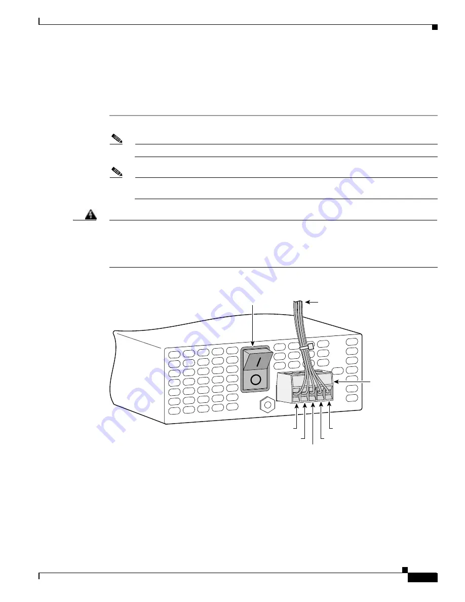
If you are using a DC-powered unit, refer to Figure B-1 or Figure B-2 and complete the Step a
through Step d.
Warning
Before performing any of the following procedures, ensure that power is removed from the DC circuit.
To ensure that all power is OFF, locate the circuit breaker on the panel board that services the DC
circuit, switch the circuit breaker to the OFF position, and tape the switch handle of the circuit
breaker in the OFF position. To see translations of the warnings that appear in this publication, refer
to the
Regulatory Compliance and Safety Information
document that accompanied this device.
Figure B-1
DC Power Supply Connections—Single Power Supply
56022
Power switch
Source A - NEG
Source A - RTN
Source B - NEG
Source B - RTN
Ground
To DC source
DC connector


