-8
Cisco AS5350 Universal Gateway Chassis Installation Guide
78-10754-03 0A
Appendix
Removing the Old Power Supply
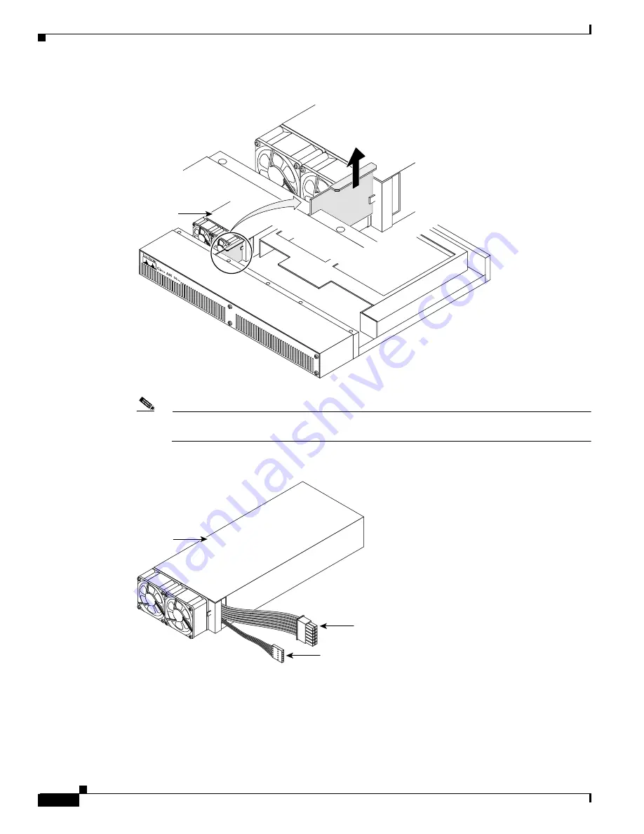
Figure B-7
Removing the Air Separator
Note
There are two power connectors on the power supply. One connects to the backplane and the
other to the system board. (See Figure B-8.)
Figure B-8
Power Supply Connectors
Step 5
Disconnect both power supply connectors. Disconnect the backplane connector first, followed by the
system board connector. (See Figure B-9.)
Power
supply
35692
3
Chassis bottom
Front panel
Power
supply
Backplane
connector
System board
connector
36016


