Cisco Firepower Threat Defense for the ASA 5506-X Series Using Firepower Device Manager Quick Start Guide
5. Power on the Firepower Threat Defense Device
7
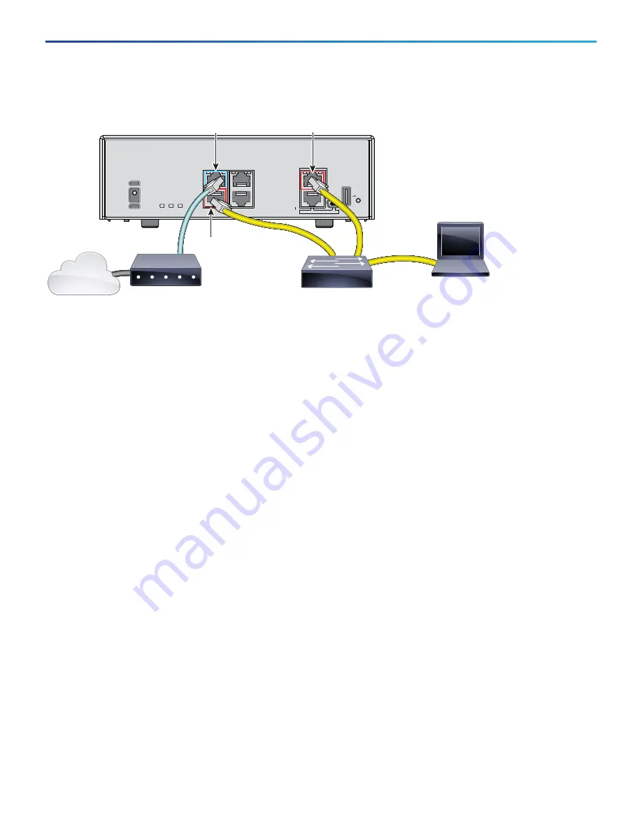
Figure 8
ASA 5506H-X for Version 6.1.
Procedure
1.
Cable the following to a Layer 2 Ethernet switch:
—
GigabitEthernet 1/2 interface (inside)
—
Management 1/1 interface (for the Firepower Device Manager)
—
A local management computer
Note:
You can connect inside and management on the same network because the management interface acts
like a separate device that belongs only to the Firepower Device Manager.
2.
Connect the GigabitEthernet 1/1 (outside) interface to your ISP/WAN modem or other outside device. By
default, the IP address is obtained using DHCP, but you can set a static address during initial configuration.
5. Power on the Firepower Threat Defense Device
Procedure
1.
Attach the power cable to the Firepower Threat Defense device and connect it to an electrical outlet.
The power turns on automatically when you plug in the power cable. There is no power button.
2.
Check the Power LED on the back of the Firepower Threat Defense device; if it is solid green, the device is
powered on.
3.
Check the Status LED on the back of the Firepower Threat Defense device; after it is solid green, the system
has passed power-on diagnostics.
6. Launch Firepower Device Manager
When you initially log into Firepower Device Manager, you are taken through the device setup wizard to complete
the initial system configuration.
Power
12VDC, 5A
Power
Status
Active
USB
RESET
GE MGMT
L
S
CONSOLE
4
3
2
1
GigabitEthernet 1/1
outside, DHCP from Modem
Management 1/1
192.168.45.45
Layer 2 Switch
WAN Modem
Management Computer
DHCP from inside: 192.168.45.x
GigabitEthernet 1/2
inside, 192.168.45.1
(Gateway)
Internet


