4-5
Cisco ASA 5585-X Adaptive Security Appliance Hardware Installation Guide
OL-22567-02
Chapter 4 Maintenance and Upgrade Procedures
Installing and Removing Cisco ASA 5585-X Network I/O Modules
Step 3
On the front panel of the SSP, ensure the HDD1 (left hard disk drive) and HDD0 (right hard disk drive)
indicators are flashing green to indicate that the drives are active.
Installing and Removing Cisco ASA 5585-X Network I/O
Modules
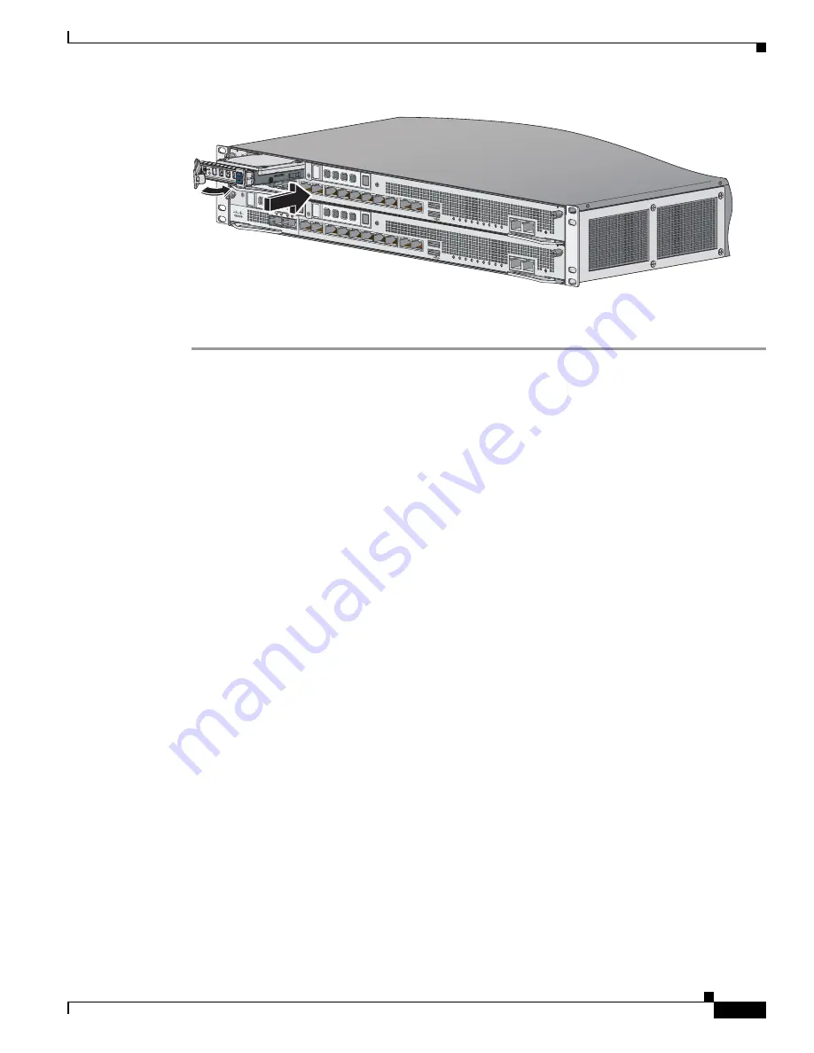
The ASA 5585-X comes with a core Security Services Processor (SSP-10, SSP-20, SSP-40, or SSP-60)
already installed in slot 0. You can install one or two of the following optional network I/O modules in
slot 1, which you divide into two slots using the accompanying slot divider:
•
Cisco ASA 5585-X 4-port 10-G Network I/O Module
•
Cisco ASA 5585-X 8-port 10-G Network I/O Module
•
Cisco ASA 5585-X 20-port 1-G Network I/O Module
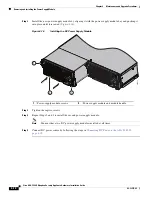
The network I/O module is not hot-swappable, so you must power off the ASA 5585-X before installing
or removing the module. You must have a Phillips head screwdriver to install the slot divider that divides
slot 1 into two bays.
The ports are numbered right to left, with port 0 being the far right port and the far left port is either port
3, 7, or 19 depending on whether you have a 4-, 8-, or 20-port module. The 20-port numbers go from top
to bottom, and right to left. For slot 1 (top right slot), the interface is named TenGigabitEthernet 1/0
through TenGigabitEthernet 1/3. For slot 2 (top left slot) the interface is named TenGigabitEthernet 2/0
through TenGigabitEthernet 2/7.
PWR
BOO
T
ALARM ACT
VPN
PS1
HDD1
PS0
HDD0
USB
RESET
0
SFP1
SFP0
1
0
1
2
3
4
5
6
7
MGMT
0
1
AUX
CONSOLE
332633
PWR
BOO
T
ALARM ACT
VPN
PS1
HDD1
PS0
HDD0
USB
RESET
0
SFP1
SFP0
1
0
1
2
3
4
5
6
7
MGMT
0
1
AUX
CONSOLE


