GGSN Support in GPRS/UMTS Wireless Data Services
▀ Features and Functionality - Optional Enhanced Feature Software
▄ Cisco ASR 5000 Series Product Overview
OL-22938-02
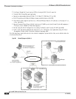
The system provides several levels of system redundancy:
Under normal N+1 packet processing card hardware redundancy, if a catastrophic packet processing card failure
occurs all affected calls are migrated to the standby packet processing card if possible. Calls which cannot be
migrated are gracefully terminated with proper call-termination signaling and accounting records are generated
with statistics accurate to the last internal checkpoint
If the Session Recovery feature is enabled, any total packet processing card failure will cause a packet
processing card switchover and all established sessions for supported call-types are recovered without any loss
of session.
Even though chassis provides excellent intra-chassis redundancy with these two schemes, certain catastrophic failures
which can cause total chassis outages, such as IP routing failures, line-cuts, loss of power, or physical destruction of the
chassis, cannot be protected by this scheme. In such cases, the GGSN Inter-Chassis Session Recovery feature provides
geographic redundancy between sites. This has the benefit of not only providing enhanced subscriber experience even
during catastrophic outages, but can also protect other systems such as the RAN from subscriber re-activation storms.
The Interchassis Session Recovery feature allows for continuous call processing without interrupting subscriber
services. This is accomplished through the use of redundant chassis. The chassis are configured as primary and backup
with one being active and one in recovery mode. A checkpoint duration timer is used to control when subscriber data is
sent from the active chassis to the inactive chassis. If the active chassis handling the call traffic goes out of service, the
inactive chassis transitions to the active state and continues processing the call traffic without interrupting the subscriber
session. The chassis determines which is active through a propriety TCP-based connection called a redundancy link.
This link is used to exchange Hello messages between the primary and backup chassis and must be maintained for
proper system operation.
Interchassis Communication
:
Chassis configured to support Interchassis Session Recovery communicate using periodic Hello messages.
These messages are sent by each chassis to notify the peer of its current state. The Hello message contains
information about the chassis such as its configuration and priority. A dead interval is used to set a time limit
for a Hello message to be received from the chassis' peer. If the standby chassis does not receive a Hello
message from the active chassis within the dead interval, the standby chassis transitions to the active state. In
situations where the redundancy link goes out of service, a priority scheme is used to determine which chassis
processes the session. The following priority scheme is used:
router identifier
chassis priority
SPIO MAC address
Checkpoint Message
:
Checkpoint messages are sent from the active chassis to the inactive chassis. Checkpoint messages are sent at
specific intervals and contain all the information needed to recreate the sessions on the standby chassis, if that
chassis were to become active. Once a session exceeds the checkpoint duration, checkpoint data is collected on
the session. The checkpoint parameter determines the amount of time a session must be active before it is
included in the checkpoint message.
Important:
For more information on inter-chassis session recovery support, refer
Interchassis Session Recovery
chapter in
System Enhanced Feature Configuration Guide
.
Summary of Contents for ASR 5000 Series
Page 1: ......
Page 26: ......
Page 48: ...New In Release 10 0 SCM Features Cisco ASR 5000 Series Product Overview OL 22938 02 ...
Page 50: ......
Page 58: ......
Page 68: ......
Page 126: ......
Page 138: ......
Page 146: ......
Page 218: ......
Page 236: ......
Page 356: ......
Page 374: ......
Page 422: ......
Page 496: ......
Page 572: ......
Page 654: ......
Page 700: ......
Page 726: ......
Page 784: ......
Page 816: ......
Page 844: ......
Page 906: ......
Page 926: ......
Page 942: ......
Page 943: ...Cisco ASR 5000 Series Product Overview OL 22938 02 Chapter 30 Technical Specifications ...
Page 966: ......
Page 972: ......

