Technical Specifications
▀ Interface Specifications
▄ Cisco ASR 5000 Series Product Overview
OL-22938-02
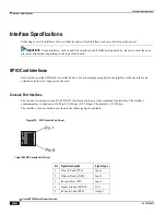
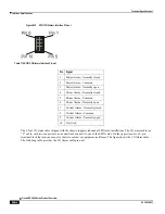
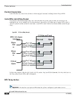
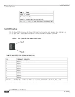
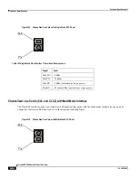
Figure 222.
SPIO CO Alarms Interface Pin-out
Table 110.
SPIO CO Alarms Interface Pin-out
Pin
Signal
1
Major Alarm - Normally closed
2
Major Alarm - Common
3
Major Alarm - Normally open
4
Minor Alarm - Normally closed
5
Minor Alarm - Common
6
Minor Alarm - Normally open
7
Critical Alarm - Normally closed
8
Critical Alarm - Common
9
Critical Alarm - Normally open
10
Not Used
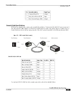
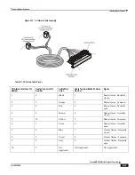
The 8-foot CO alarm cable shipped with the chassis supports redundant SPIO card installations. The CO alarm cable is a
―Y‖ cable, with two connectors on one end. Each connects to one of the SPIO cards. On the opposite end is a 9-pin
terminal block that you can mount to the telco cabinet or equipment rack frame. The figure shows the CO Alarm cable.
The following table provides the CO Alarm cable pin-outs.
Summary of Contents for ASR 5000 Series
Page 1: ......
Page 26: ......
Page 48: ...New In Release 10 0 SCM Features Cisco ASR 5000 Series Product Overview OL 22938 02 ...
Page 50: ......
Page 58: ......
Page 68: ......
Page 126: ......
Page 138: ......
Page 146: ......
Page 218: ......
Page 236: ......
Page 356: ......
Page 374: ......
Page 422: ......
Page 496: ......
Page 572: ......
Page 654: ......
Page 700: ......
Page 726: ......
Page 784: ......
Page 816: ......
Page 844: ......
Page 906: ......
Page 926: ......
Page 942: ......
Page 943: ...Cisco ASR 5000 Series Product Overview OL 22938 02 Chapter 30 Technical Specifications ...
Page 966: ......
Page 972: ......

