Packet Data Interworking Function Overview
▀ Features and Functionality - Licensed Enhanced Feature Support
▄ Cisco ASR 5000 Series Product Overview
OL-22938-02
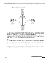
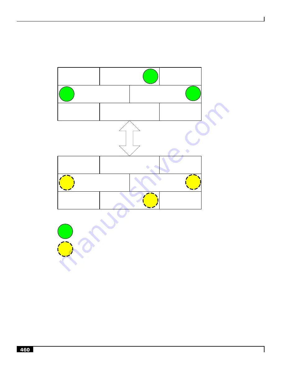
Figure 124.
Loopback Interface Configuration
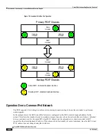
Primary PDIF Chassis
AAA
Context
I/F
C
Ingress
Context
I/F
A
Egress
Context
I/F
B
SRP
Context
S
R
P
L
in
k
AAA
Context
I/F
C
Ingress
Context
I/F
A
Egress
Context
I/F
B
SRP
Context
I/F
A
Backup PDIF Chassis
I/F
A
Active SRP
– Activated loopback interface
Standby SRP
– Activated loopback interface
Operation Over a Common IPv4 Network
The PDIF supports L2 switching to enable carriers not using dynamic routing between the core nodes to perform an
online upgrade.
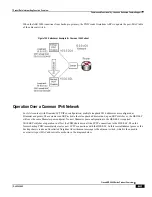
In the example below, the SRP virtual MAC address is configured for the SRP-activated loopback address for the
subnet. This allows the standby chassis to seamlessly assume the active role in the network after a switchover. Attached
devices continue to send to the same SRP virtual MAC address and the currently active chassis responds to ARP
requests for the shared loopback IP address. This scheme allows fast standby-to-active transitions, since the SRP virtual
MAC address does not change during the switchover.
Summary of Contents for ASR 5000 Series
Page 1: ......
Page 26: ......
Page 48: ...New In Release 10 0 SCM Features Cisco ASR 5000 Series Product Overview OL 22938 02 ...
Page 50: ......
Page 58: ......
Page 68: ......
Page 126: ......
Page 138: ......
Page 146: ......
Page 218: ......
Page 236: ......
Page 356: ......
Page 374: ......
Page 422: ......
Page 496: ......
Page 572: ......
Page 654: ......
Page 700: ......
Page 726: ......
Page 784: ......
Page 816: ......
Page 844: ......
Page 906: ......
Page 926: ......
Page 942: ......
Page 943: ...Cisco ASR 5000 Series Product Overview OL 22938 02 Chapter 30 Technical Specifications ...
Page 966: ......
Page 972: ......

