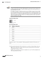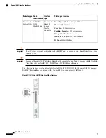
Refer to the following figure and table for pinouts for the RJ-45 Ethernet ports.
Figure 42: 10/100 Ethernet Interface Pinouts
Table 39: 10/100 Ethernet Interface Pinouts 0
100Base-T 100Mbps Cat5
Pin
TX+
1
TX-
2
RX+
3
Not applicable
4
Not applicable
5
RX-
6
Not applicable
7
Not applicable
8
RX = Receive Data TX = Transmit Data
Be sure to label the interface cables with their destinations prior to connecting them to the FLC2. This
will assure proper reconnection should the card need to be serviced.
Important
To cable the FLC2, simply plug an STC Ethernet cable from a network device into the desired port.
ASR 5000 Installation Guide
105
Cabling the Fast Ethernet (10/100) Line Card
FLC2 Interfaces
Summary of Contents for ASR 5000
Page 16: ...ASR 5000 Installation Guide xvi About this Guide Contacting Customer Support ...
Page 64: ...ASR 5000 Installation Guide 48 Installation Procedure Overview Laser Notice ...
Page 100: ...ASR 5000 Installation Guide 84 Line Card Installation Installing the XGLC ...
Page 122: ...ASR 5000 Installation Guide 106 Cabling the Fast Ethernet 10 100 Line Card FLC2 Interfaces ...
Page 206: ...ASR 5000 Installation Guide 190 Removing and Installing SMC PC Cards Removing PC Cards ...
Page 212: ...ASR 5000 Installation Guide 196 Replacing the Chassis Air Filter Installing the Air Filter ...
Page 220: ...ASR 5000 Installation Guide 204 Replacing a Power Filter Unit What to do with the Failed PFU ...
Page 266: ...ASR 5000 Installation Guide 250 Safety Electrical and EMC Certifications Korean EMC ...
Page 270: ...ASR 5000 Installation Guide 254 Environmental Specifications Chassis Air Flow ...


