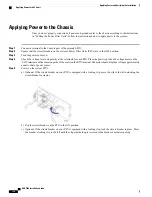
d) Repeat step a through step c for the second PFU.
Verifying the Installation
When power is applied to the chassis, power is provided to the upper and lower fan trays, and every installed
application and line card.
Each PFU, application card, and line card installed in the chassis has light emitting diodes (LEDs) that indicate
its status. This section describes how to interpret the LEDs to verify that all of the installed components are
functioning properly.
As the system progresses through its boot process, some cards may have no immediate LED activity. Line
cards have sporadic Link and Activity LED activity. It is recommended that you allow several minutes to
elapse prior to checking the LEDs on the various cards to verify the installation.
Important
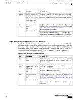
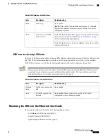
Checking the LED on the PFU
Each PFU has a single status LED labeled POWER. This LED is green during normal operating conditions.
ASR 5000 Installation Guide
137
Applying Power and Verifying the Installation
Verifying the Installation
Summary of Contents for ASR 5000
Page 16: ...ASR 5000 Installation Guide xvi About this Guide Contacting Customer Support ...
Page 64: ...ASR 5000 Installation Guide 48 Installation Procedure Overview Laser Notice ...
Page 100: ...ASR 5000 Installation Guide 84 Line Card Installation Installing the XGLC ...
Page 122: ...ASR 5000 Installation Guide 106 Cabling the Fast Ethernet 10 100 Line Card FLC2 Interfaces ...
Page 206: ...ASR 5000 Installation Guide 190 Removing and Installing SMC PC Cards Removing PC Cards ...
Page 212: ...ASR 5000 Installation Guide 196 Replacing the Chassis Air Filter Installing the Air Filter ...
Page 220: ...ASR 5000 Installation Guide 204 Replacing a Power Filter Unit What to do with the Failed PFU ...
Page 266: ...ASR 5000 Installation Guide 250 Safety Electrical and EMC Certifications Korean EMC ...
Page 270: ...ASR 5000 Installation Guide 254 Environmental Specifications Chassis Air Flow ...


