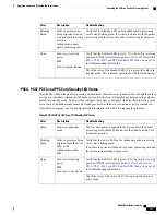
Troubleshooting
Description
Color
Verify that the Run/Fail LED is green. If so, the card is receiving
power and POST test results are positive. If it is off, refer to
Run/Fail LED States, on page 148
for troubleshooting information.
Card is not receiving
power.
OR
Card is in Standby Mode.
None
Check the state of the Standby LED. If it is green, the card is in
standby mode. Refer to the
System Administration Guide
for
information on making the card active
SPIO Standby LED States
The Standby LED on the SPIO indicates that software is loaded on the card and that it is serving as a redundant
component. For the SPIO installed in slot 25, this LED is illuminated steady green during normal operation.
For the SPIO installed in slot 24, this LED is off during normal operation.
If the LED is not green, use the troubleshooting information in the table to diagnose the problem.
Table 61: SPIO Standby LED States
Troubleshooting
Description
Color
None needed for SPIO in slot 25. If green for SPIO in slot 24,
check the status of the SMC installed in slot 8.
If the SMC in slot 8 is in standby mode, it is possible that there
is a configuration problem.
Card is in redundant
mode
Green
Verify that the Run/Fail LED is green. If so, the card is receiving
power and POST test results are positive. If it is off, refer to
Run/Fail LED States, on page 148
for troubleshooting information.
Card is not receiving
power.
OR
Card is in Active Mode.
None
Check the state of the Active LED. If it is green, the card is in
active mode.
SPIO Interface Link LED States
The Link LED, associated with a particular SPIO interface indicates the status of the network link. This LED
is illuminated steady green during normal operation.
If the LED is not green, use the troubleshooting information in the table to diagnose the problem.
During system startup, some Link and/or Activity LEDs may momentarily illuminate. This activity is
normal and does not indicate any network link or data transfer status. The line card has not yet been
initialized and placed into a stable operational state by the system.
Important
ASR 5000 Installation Guide
150
Applying Power and Verifying the Installation
Checking the LEDs on the SPIO(s)
Summary of Contents for ASR 5000
Page 16: ...ASR 5000 Installation Guide xvi About this Guide Contacting Customer Support ...
Page 64: ...ASR 5000 Installation Guide 48 Installation Procedure Overview Laser Notice ...
Page 100: ...ASR 5000 Installation Guide 84 Line Card Installation Installing the XGLC ...
Page 122: ...ASR 5000 Installation Guide 106 Cabling the Fast Ethernet 10 100 Line Card FLC2 Interfaces ...
Page 206: ...ASR 5000 Installation Guide 190 Removing and Installing SMC PC Cards Removing PC Cards ...
Page 212: ...ASR 5000 Installation Guide 196 Replacing the Chassis Air Filter Installing the Air Filter ...
Page 220: ...ASR 5000 Installation Guide 204 Replacing a Power Filter Unit What to do with the Failed PFU ...
Page 266: ...ASR 5000 Installation Guide 250 Safety Electrical and EMC Certifications Korean EMC ...
Page 270: ...ASR 5000 Installation Guide 254 Environmental Specifications Chassis Air Flow ...

