Troubleshooting
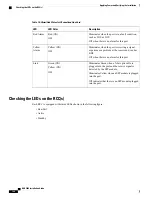
Description
Color
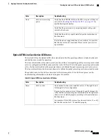
Verify that the POWER LEDs on the PFUs are green. If they are
not, refer to
Checking the LED on the PFU, on page 137
for
troubleshooting information.
Card powered with
error(s) detected
None
Verify that the power source is supplying ample voltage and
current to the chassis.
Verify that the card is properly installed per the instructions in
this document.
If all of the above suggestions have been verified, it is possible
that the RCC is not functional. Please contact your service
representative.
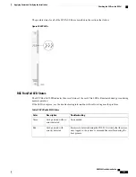
RCC Active LED States
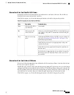
The Active LED on the RCC indicates that the card is being used. During normal operation, this LED is off
on both RCCs.
If the LED is not green, use the troubleshooting information in the table to diagnose the problem.
Table 78: RCC Active LED States
Troubleshooting
Description
Color
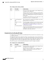
The RCC is actively routing traffic from a line card installed
behind a packet processing card that has failed to a redundant
packet processing card.
The RCC installed in chassis slot 40 processes traffic for the line
cards in chassis slots 17 through 23 and 26 through 32. The RCC
installed in chassis slot 41 processes traffic for the line cards in
slots 33 through 39 and 42 through 48.
See
Checking the LEDs on Packet Processing Cards, on page
144
to determine which packet processing card has failed.
Information on determining the cause of the failure can be found
in the
System Administration Guide
.
Card is active
Green
Verify that the Run/Fail LED is green. If so, the card is receiving
power and POST test results are positive. If it is off, refer to
Run/Fail LED States, on page 165
for troubleshooting information.
Card is not receiving
power
OR
Card in
Standby Mode
None
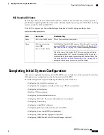
Check the state of the Standby LED. If it is green, the card is in
standby mode. This is the normal operating mode.
ASR 5000 Installation Guide
166
Applying Power and Verifying the Installation
Checking the LEDs on the RCC(s)
Summary of Contents for ASR 5000
Page 16: ...ASR 5000 Installation Guide xvi About this Guide Contacting Customer Support ...
Page 64: ...ASR 5000 Installation Guide 48 Installation Procedure Overview Laser Notice ...
Page 100: ...ASR 5000 Installation Guide 84 Line Card Installation Installing the XGLC ...
Page 122: ...ASR 5000 Installation Guide 106 Cabling the Fast Ethernet 10 100 Line Card FLC2 Interfaces ...
Page 206: ...ASR 5000 Installation Guide 190 Removing and Installing SMC PC Cards Removing PC Cards ...
Page 212: ...ASR 5000 Installation Guide 196 Replacing the Chassis Air Filter Installing the Air Filter ...
Page 220: ...ASR 5000 Installation Guide 204 Replacing a Power Filter Unit What to do with the Failed PFU ...
Page 266: ...ASR 5000 Installation Guide 250 Safety Electrical and EMC Certifications Korean EMC ...
Page 270: ...ASR 5000 Installation Guide 254 Environmental Specifications Chassis Air Flow ...

