Signal
DB-25 Pin
RJ-45 Pin
Signal Type
Signal Description
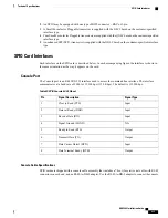
RTS
4
5
Output
Ready to Send (RTS)
TxD
2
6
Input
Transmit Data (TX)
DCD
8
7
Output
Data Carrier Detect (DCD)
DTR
20
8
Output
Data Terminal Ready (DTR)
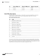
Fiber SFP Interface
The fiber Small Form-factor Pluggable (SFP) interface has two host connectors that transmit and receive data.
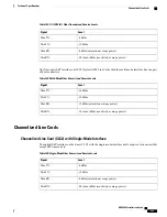
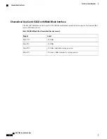
Table 92: Fiber SFP Interface Transmit and Receive Levels
Level
Signal
0 dBm
Max TX:
-9.5 dBm
Min TX:
0 dBm (saturation average power)
Max RX:
-20 (typical) / -17 (max.) dBm (sensitivity average power)
Min RX:
10/100/1000 Mbps RJ-45 Interface
The two RJ-45 interfaces are auto-sensing 10/100/1000 Ethernet (10Base-T/100Base-TX/1000Base-T) that
require unshielded twisted pair (UTP) copper cable.
Table 93: SPIO RJ-45 Ethernet Interface Pinouts
1000Base-Tx 1Gbps Cat5+
100Base-Tx 100Mbps Cat5
10Base-T 10Mbps Cat3
Pin
BI DA+
TX+
TX+
1
BI DA-
TX-
TX-
2
BI DB+
RX+
RX+
3
BI DC+
Not used
Not used
4
BI DC-
Not used
Not used
5
BI DB-
RX-
RX-
6
ASR 5000 Installation Guide
237
Technical Specifications
SPIO Card Interfaces
Summary of Contents for ASR 5000
Page 16: ...ASR 5000 Installation Guide xvi About this Guide Contacting Customer Support ...
Page 64: ...ASR 5000 Installation Guide 48 Installation Procedure Overview Laser Notice ...
Page 100: ...ASR 5000 Installation Guide 84 Line Card Installation Installing the XGLC ...
Page 122: ...ASR 5000 Installation Guide 106 Cabling the Fast Ethernet 10 100 Line Card FLC2 Interfaces ...
Page 206: ...ASR 5000 Installation Guide 190 Removing and Installing SMC PC Cards Removing PC Cards ...
Page 212: ...ASR 5000 Installation Guide 196 Replacing the Chassis Air Filter Installing the Air Filter ...
Page 220: ...ASR 5000 Installation Guide 204 Replacing a Power Filter Unit What to do with the Failed PFU ...
Page 266: ...ASR 5000 Installation Guide 250 Safety Electrical and EMC Certifications Korean EMC ...
Page 270: ...ASR 5000 Installation Guide 254 Environmental Specifications Chassis Air Flow ...


